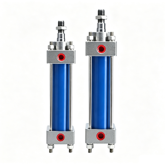
High-pressure oil from the hydraulic pump enters the cylinder barrel and acts upon the piston’s pressure-bearing surface, generating thrust that drives the movement of the piston and piston rod. Reversing the direction of oil flow enables extension and retraction; adjusting the flow rate controls the speed of movement, while regulating the oil pressure controls the magnitude of the output force.
20 ans d'expérience dans le secteur industriel, au service de solutions sur mesure adaptées à vos spécifications précises et à vos besoins de production.
Plus de 20 ans d'expérienceLa qualité de nos produits n'a rien à envier à celle des grandes marques, car nous respectons scrupuleusement les normes techniques des plus grandes marques nationales et internationales.
Qualité conforme aux normes ISOSituée à Liushi, dans la ville de Yueqing, à Wenzhou, dans la province du Zhejiang, en Chine, notre entreprise dispose d'une chaîne d'approvisionnement complète en composants, d'équipements haut de gamme de pointe et d'une longue tradition de fabrication.
Prix d'usinehydraulic cylinder is an actuator in a hydraulic system that converts the pressure energy of hydraulic fluid into mechanical energy,
producing linear reciprocating motion (or, in a few cases,
oscillating motion) as well as outputting thrust or pulling force and speed.
It is commonly referred to as an oil cylinder.
| Diamètre intérieur (mm) | 32 | 40 | 50 | 63 | 80 | 100 | 125 | 150 | 180 | 200 | 225 | 250 |
|---|---|---|---|---|---|---|---|---|---|---|---|---|
| Type d'action | Double effet | |||||||||||
| Milieu de travail | General mineral oil, water-based fluid, water-oil emulsion, oil-water emulsion, phosphate ester fluid | |||||||||||
| Température de fonctionnement | −10°C ~ +80°C, up to +200°C with high-temperature resistant materials | |||||||||||
| Viscosité du fluide | 20~400mm²/s (cSt) | |||||||||||
| Plage de vitesses de fonctionnement | 500mm/s | |||||||||||
| Fil de discussion sur Port | RC3/8 | RC3/8 | RC3/8 | RC1/2 | RC1/2 | RC3/4 | RC3/4 | RC3/4 | G1 | G1 | G1 1/4 | G1 1/4 |
| Grade C Piston Rod Dia.(mm) | 16 | 20 | 25 | 30 | 35 | 40 | 56 | 65 | 80 | 90 | 100 | 110 |
| Grade B Piston Rod Dia.(mm) | 20 | 25 | 30 | 35 | 40 | 56 | 70 | 85 | 100 | 110 | 125 | 140 |
| Cushion Length (mm) | 20 | 20 | 20 | 20 | 25 | 25 | 25 | 25 | 30 | 30 | 30 | 35 |
| Course maximale (mm) | 5000 | |||||||||||
Code de commande actuel :
Remarque :
1. Standard HOB-70 equipped with Grade C rod, HOB-140 equipped with Grade B rod.
2. If non-standard rod matching (HOB-70 with Grade B rod or HOB-140 with Grade C rod), please specify when ordering.
3. For other non-standard requirements, please contact our sales staff.
▲ Blank field represents standard product, no marking required for ordering.
| Diamètre intérieur (mm) | 32 | 40 | 50 | 63 | 80 | 100 | 125 |
|---|---|---|---|---|---|---|---|
| Type d'action | Double effet | ||||||
| Milieu de travail | Clean standard hydraulic oil | ||||||
| Température de fonctionnement | -10~60°C | ||||||
| Plage de pression de service | 0.8~7 MPa | ||||||
| Plage de vitesses de fonctionnement | 0~300 mm/s | ||||||
| Piston Rod Dia.(mm) | 16 | 20 | 20 | 25 | 30 | 35 | 50 |
| Standard Piston Length (mm) | 30 | 30 | 30 | 35 | 35 | 50 | 50 |
| Custom Stroke 1501~2500mm, Piston Length (mm) | 60 | 60 | 60 | 60 | 70 | 100 | 100 |
| Custom Stroke 2501~4000mm, Piston Length (mm) | 120 | 120 | 120 | 120 | 140 | 150 | 150 |
| Fil de discussion sur Port | PT1/4 | PT3/8 | PT3/8 | PT3/8 | PT1/2 | PT1/2 | PT1/2 |
| Course maximale (mm) | 4000 | ||||||
| Remarque : filetage PT (en option), filetage G, filetage NPT. Veuillez nous contacter pour toute autre exigence particulière. | |||||||
Code de commande actuel :
Remarque :
1. MOB / MOD series light hydraulic cylinder, standard working pressure: 7MPa.
2. Blank code represents standard configuration, no mark required for ordering.
▲ For non-standard requirements, please contact our sales staff.
! ! ! If the model information is not updated in real-time, you can select the required specifications yourself, note down the model number, and contact us for further details.

HSG series consists of double-acting, single-rod industrial hydraulic cylinders designed as standard units for construction machinery.
These cylinders feature precision-honed barrels, hard-chrome plated piston rods, and reliable sealing systems. They are available in three rated pressure classes—16 MPa (E), 21 MPa (F), and 32 MPa (H)—and offer three speed ratios.
They support various mounting configurations and optional cushioning mechanisms. Standard stroke lengths increase in 50 mm increments, and custom specifications are available. They are suitable for equipment such as loaders, sanitation vehicles, and agricultural machinery.
| Diamètre intérieur (mm) | 40 | 50 | 63 | 80 | 90 | 100 | 110 | 125 | 140 | 150 | 160 | 180 | 200 | 220 | 250 |
|---|---|---|---|---|---|---|---|---|---|---|---|---|---|---|---|
| Type d'action | Double-acting Single Rod Hydraulic Cylinder | ||||||||||||||
| Milieu de travail | Mineral hydraulic oil (ISO VG32/46) | ||||||||||||||
| Température de fonctionnement | -20℃ ~ +80℃ | ||||||||||||||
| Plage de pression de service | Class E: 16 MPa; Class F: 21 MPa; Class H: 32 MPa | ||||||||||||||
| Plage de vitesses de fonctionnement | 0~300 mm/s | ||||||||||||||
| Speed Ratio 1.33, Piston Rod Dia.(mm) (Thin Rod) | 20 | 25 | 32 | 40 | 45 | 50 | 55 | 63 | 70 | 80 | 80 | 90 | 100 | 110 | 125 |
| Speed Ratio 1.46, Piston Rod Dia.(mm) (Standard Rod) | 22 | 28 | 35 | 45 | 50 | 55 | 63 | 70 | 80 | 90 | 90 | 100 | 110 | 125 | 140 |
| Speed Ratio 2, Piston Rod Dia.(mm) (Thick Rod) | 25 | 32 | 45 | .. | 55 | 70 | 80 | 90 | 100 | 110 | 110 | 125 | 140 | 160 | 180 |
| Fil de discussion sur Port | M14*1,5 | M18*1,5 | M18*1,5 | M22*1,5 | M22*1,5 | M27*2 | M27*2 | M27*2 | M27*2 | M33*2 | M33*2 | M42*2 | M42*2 | M42*2 | M42*2 |
| Course maximale (mm) | 2000 | ||||||||||||||
| Remarque : filetage PT (en option), filetage G, filetage NPT. Veuillez nous contacter pour toute autre exigence particulière. | |||||||||||||||
Code de commande actuel :
Remarques :
1. HSG Series Heavy Duty Hydraulic Cylinder.
2. Some mounting styles have bore restrictions, please refer to technical datasheet.
▲ For non-standard requirements, please contact sales.

The ROB series round hydraulic cylinder features a compact, lightweight round-body design. It supports the installation of a limit nut for adjustable stroke, allowing the effective extension stroke to be shortened as desired within the cylinder’s total range; it offers high adjustment precision and easy installation.
With a rated pressure of 14 MPa and a compact footprint, it is widely used in applications such as workholding fixtures, small-scale automation equipment, and mold ejection. A full range of specifications is available in stock, and custom configurations can be provided upon request.
| Bore(Inner Dia,mm) | 20 | 32 | 40 | 50 | 63 | 80 | 100 | 125 | 160 | 200 | 250 | 320 | 400 | 500 |
|---|---|---|---|---|---|---|---|---|---|---|---|---|---|---|
| Type d'action | Double effet | |||||||||||||
| Milieu de travail | Mineral Hydraulic Oil (ISO VG32/46) | |||||||||||||
| Working Temp. | -10℃ ~ +80℃ | |||||||||||||
| Max Working Pressure | 7 Mpa & 16 Mpa | |||||||||||||
| Max Test Pressure | 14 Mpa & 24 Mpa | |||||||||||||
| Grade C Rod Dia(mm) | 16 | 18 | 22 | 28 | 36 | 45 | 56 | 70 | 90 | 110 | 140 | 180 | 220 | 280 |
| Grade B Rod Dia(mm) | 18 | 22 | 28 | 36 | 45 | 56 | 70 | 90 | 112 | 140 | 180 | 220 | 280 | 360 |
| Fil de discussion sur Port | RC1/8 | RC1/4 | RC3/8 | RC3/8 | RC1/2 | RC1/2 | RC3/4 | RC3/4 | RC1 | RC1 | RC1 1/4 | RC1 1/4 | RC1 1/2 | RC1 1/2 |
| Max Stroke(mm) | 1000 | |||||||||||||
| Note: Port thread optional PT, G, NPT thread. Please contact us for other special requirements. | ||||||||||||||
Code de commande généré :
Remarque :
1. Blank means standard configuration, no mark required for ordering.
2. New mounting options: FC Front Round Flange, FD Rear Round Flange, CAI With Spherical Bearing.
3. Adjustable stroke must be smaller than standard stroke, invalid selection will be greyed out.
4. Cylinders with cushion have different end cap OD, please contact us for details.
▲ For non-standard stroke or special requirements, please contact our sales department.

| Diamètre intérieur (mm) | 20 | 25 | 32 | 40 | 50 | 63 | 80 | 100 |
|---|---|---|---|---|---|---|---|---|
| Type d'action | À double effet | |||||||
| Milieu de travail | Mineral hydraulic oil (ISO VG32/46) | |||||||
| Température de fonctionnement | -10℃ ~ +80℃ | |||||||
| Plage de pression de service | 70kgf/cm² and 140kgf/cm² | |||||||
| Viscosity | 20~400 mm²/s (cst) | |||||||
| Piston Rod Dia.(mm) | 12 | 14 | 20 | 25 | 30 | 35 | 40 | 56 |
| Fil de discussion sur Port | RC1/8 | RC1/8 | RC1/4 | RC1/4 | RC1/4 | RC1/4 | RC3/8 | RC3/8 |
| Course maximale (mm) | 200 | |||||||
| Remarque : filetage PT (en option), filetage G, filetage NPT. Veuillez nous contacter pour toute autre exigence particulière. | ||||||||
Code de commande actuel :
Remarques :
1. Blank field = standard configuration, no marking required on order.
2. Oil inlet position: only available for MF manifold mount cylinder, leave blank for other types.
3. Adjustable stroke: only applicable for Type D double rod cylinder. Suffix ST only shows for adjustable stroke.
4. Heat & acid resistant feature(J) is NOT available for MF manifold mount cylinder.
5. LA Radial Mount only valid for bore:32,40,50,63,80,100.
6. Max allowable stroke varies by bore size. Stroke options exceeding limit will be disabled automatically.
▲ Please contact sales for stroke beyond standard range or invalid bore & stroke combination.
| Bore(Inner Dia,mm) | 25 | 32 | 40 | 50 | 63 |
|---|---|---|---|---|---|
| Type d'action | Double effet | ||||
| Milieu de travail | General hydraulic oil equivalent to ISO-VG-32 viscosity grade | ||||
| Température de fonctionnement | -10 °C à +70 °C | ||||
| Working Pressure Range | 15kgf/cm² ~ 70kgf/cm² | ||||
| Theoretical Clamping Force @70kgf/cm² (N) | 166 | 343 | 603 | 943 | 1488 |
| Rotation Stroke (mm) | 9 | 11 | 11 | 13 | 13 |
| Standard Vertical Stroke (mm) | 13 | 15 | 15 | 17 | 17 |
| Extended Vertical Stroke (mm) | -- | 30 | 30 | 34 | 34 |
| Standard Total Stroke (mm) | 22 | 26 | 26 | 30 | 30 |
| Extended Total Stroke (mm) | -- | 41 | 41 | 47 | 47 |
| Rod Diameter (mm) | 18 | 20 | 22.4 | 28 | 35 |
| Fil de discussion sur Port | PT1/8 | PT1/8 | PT1/8 | PT1/4 | PT1/4 |
| Remarque : filetage PT (en option), filetage G, filetage NPT. Veuillez nous contacter pour toute autre exigence particulière. | |||||
Code de commande généré :
Remarque :
1. Blank means standard configuration, no mark required for ordering.
2. Custom swing angle, please refer to specification dimension sheet.
▲ For non-standard stroke or special requirements, please contact sales department.
| Modèle | Structure | Rated Pressure | Test Pressure | Bore Range | Course standard | Caractéristiques principales | Selection Guide (Applicable / Not Applicable) |
|---|---|---|---|---|---|---|---|
| MOB | Tie-rod Light Cylinder | 7MPa | 10.5MPa | 30~125mm | 50~1000mm | Low pressure tie-rod, cost-effective, easy maintenance, optional cushion | Applicable: Conveying, pusher, simple fixture, low-pressure hydraulic station (≤7MPa); Not applicable: High pressure, impact, large side force |
| HOB | Tie-rod Heavy Cylinder | 14MPa | 21MPa | 40~250mm | Max 5000mm | Medium-high pressure tie-rod, high standardization, full accessories, magnetic sensor available | Applicable: Machine tool, woodworking machinery, injection aux, hydraulic fixture, 14MPa station; Not applicable: Heavy impact, dusty outdoor, extra large bore |
| ROB | Round Welded Cylinder (No Tie-rod) | 14MPa | 21MPa | 32~200mm | 5~10000mm | Tube welded, compact size, better side load resistance than tie-rod type | Applicable: Limited space, partial side force, packaging machine, lifting equipment, custom long stroke; Not applicable: Frequent disassembly & maintenance, ultra-thin space |
| CX-SD | Thin Block Cylinder | 14MPa | 21MPa | 20~100mm | 5~100mm | Ultra-short mounting length, block body, short stroke, dedicated for mold clamping | Applicable: Injection mold, die casting mold, CNC fixture, narrow space short-stroke clamping; Not applicable: Long stroke push/pull, side force, high-speed reciprocation |
| HSG | Engineering Welded Cylinder | 16MPa (21MPa optional) | 25MPa | 40~250mm, large bore available | Depends on bore, max 12×D | Standard welded cylinder for construction machinery, anti-impact, heavy load, optional cushion | Applicable: Loader, dumper, sanitation, mining, lifting & heavy mobile equipment; Not applicable: Precision automation, narrow space, fixed fixture clamping |
| HSC | Rotary Clamp Cylinder | 7~14MPa | 10.5~21MPa | 20~63mm | 10~50mm (rotate + down stroke) | Rotate 90°/180° with clamping, large clamping force, small footprint, fixture dedicated | Applicable: Work fixture, welding jig, auto production line clamping, mold fixing; Not applicable: Long stroke push/pull, straight linear motion, large side force |
Les noms de marques mentionnés sur ce site web sont cités uniquement à titre de référence concernant les normes techniques. Ce produit n'est pas un produit original de la marque en question et n'est pas agréé par celle-ci. Il est fabriqué conformément aux spécifications techniques de la marque correspondante et présente un aspect similaire ; toutefois, il s'agit d'un produit développé de manière indépendante et n'a aucun lien avec la marque en question.
High output force and compact size;
Easy speed regulation, capable of smooth low-speed movement;
Overload protection is easily implemented;
Flexible layout, capable of long-distance power transmission.
Alimentation des sacs, tête de soudure, vanne de la trémie, pliage des rabats des cartons, poussoir de déchargement
Positionnement et serrage des pièces, mécanismes de levage pour le chargement et le déchargement, mécanismes d'arrêt et emmanchement à la presse des composants.
Positionnement des gabarits de soudage, serrage des pièces et transfert des composants
Dispositifs d'arrêt pour chaînes de montage, poussoirs de tri et dispositifs de levage de palettes.
Ouverture et fermeture de la porte de la machine-outil, alimentation en pièces à usiner et éjection des rebuts.
Plaque de guidage pour convoyeur, dispositif de maintien simple (version en acier inoxydable disponible pour les environnements humides)
MYFEQD propose une gamme complète de Hydraulic cylinders solutions.
Nos actionneurs pneumatiques sont conformes aux normes techniques des plus grandes marques mondiales,
proposant des solutions rapides pour la sélection de modèles dans divers secteurs industriels
systèmes pneumatiques.
External leakage: Oil seepage is visible to the naked eye at the piston rod, cylinder head, or oil ports; this is usually caused by damaged rod seals, dust wipers, or O-rings, loose bolts, or scratches on the piston rod.
Internal leakage: No oil is visible externally, but the load drifts downward on its own or the cylinder lacks power under load. Simple test: Extend the cylinder and maintain pressure, then disconnect the return port; if oil continues to flow out, it indicates internal leakage past the piston seal.
Not necessarily. First, identify the location of the fault:
Cylinder assembly: Worn piston seals or scored cylinder barrel → internal leakage;
Hydraulic system: Stuck relief valve / insufficient pressure setting, worn hydraulic pump, or clogged suction filter;
Fluid issues: Contamination or incorrect viscosity.
It is recommended to measure the system pressure and rule out valve or pump issues before dismantling the cylinder.
The most common cause is air entering the cylinder or piping; other causes include uneven seal friction, mechanical guide rail binding, excessive hydraulic fluid viscosity at low temperatures, and scoring of the cylinder bore.
Remedies: Cycle the cylinder through its full stroke multiple times to bleed air, check for mechanical coaxiality, and preheat the hydraulic fluid in cold conditions.
Failure of the cylinder’s built-in cushioning mechanism: the cushioning orifice is too large, or the cushioning check valve has a poor seal.
The cushioning adjustment screw can be fine-tuned; do not close the orifice completely. If the load inertia is high, an external relief-type cushioning valve can be added.
Humming/bubbling sound: Air ingress;
Friction/scraping sound: Scored piston rod, foreign object stuck in the dust seal, or scored cylinder bore;
Clanking/banging sound: Cushioning failure or mechanical misalignment;
Periodic abnormal noise: Loose piston nut.
Normal working conditions (clean hydraulic oil, temperature 40~55℃, no dust): sealed for 1~2 years.
Key points to extend the service life: Regularly filter and replace the oil; install a dust ring to prevent dust and sand from scratching the piston rod; avoid eccentric load and lateral force; the oil temperature should not exceed 80°C.
The key requirement is to prevent lateral forces caused by off-center loading.
Ensure the cylinder axis is aligned with the direction of the load’s movement;
Hinged mounts must allow the pivot pin to swing freely;
Avoid subjecting the piston rod to radial loads, as this can easily damage the rod seal and score the rod surface;
Tighten bolts evenly in a diagonal pattern.
Minor rust spots can be removed by polishing; however, scratches or peeling of the chrome plating will quickly damage the dust seal and rod seal, leading to rapid oil leakage. In such cases, refinishing the plating or replacing the piston rod is recommended.
① Excessive internal leakage, causing heat generation due to throttling within the cylinder; ② Continuous relief valve discharge; ③ Insufficient or deteriorated hydraulic fluid; ④ Excessive frictional resistance (misalignment during assembly, seals tightened too much).
The difference in effective areas of a single-rod hydraulic cylinder naturally results in unequal speeds: the area of the cap end (rodless side) is larger, yielding higher extension thrust but slower speed; the area of the rod end is smaller, yielding lower retraction thrust but faster speed. If the speed discrepancy significantly exceeds theoretical values, check for flow restriction or internal leakage.
Installation is possible, but inverted or horizontal mounting makes air accumulation more likely, necessitating the provision of an air vent and periodic bleeding. With horizontal mounting, the weight of the piston rod generates lateral force; therefore, it is preferable to use a cylinder equipped with guide supports.
Bore diameter, rod diameter, stroke, working pressure, mounting style (flange/clevis), medium (hydraulic oil), operating temperature, load, and cushioning requirement.
① Return line blockage or crushed oil pipe; ② directional control valve spool stuck, preventing shifting; ③ counterbalance valve or pilot-operated check valve failing to open; ④ cushioning check valve seized; ⑤ severe damage to piston seals, causing internal leakage (bypass). Inspect the valves and hydraulic lines first, then check the cylinder assembly itself.
Not necessarily. There are three possible sources of downward drift: internal leakage past the cylinder piston seal, leakage in the hydraulic lock (pilot-operated check valve), or leakage through the directional control valve in its neutral position. A simple diagnostic method is to lock the cylinder and isolate it from the directional control valve; by observing whether the drift continues, you can determine whether the issue lies with the cylinder or the valve. For vertical loads, the use of a hydraulic lock is strongly recommended; one should not rely solely on the cylinder seal to maintain pressure.
At low temperatures, rubber seals harden and shrink, causing the sealing gap to widen and resulting in temporary leakage; the seals regain their elasticity once the oil temperature rises. If this condition persists, it is recommended to replace the seals with low-temperature-rated materials and select a suitable low-temperature hydraulic oil.
① Fluid contamination, with solid particles causing continuous abrasion of the seal; ② Prolonged oil temperatures exceeding 80°C, accelerating seal aging; ③ Incompatibility between the fluid medium and the seal material (e.g., synthetic esters corroding standard NBR seals); ④ Scratching of the seal lip during installation; ⑤ Continuous off-center loading, causing one-sided friction on the piston rod.
This is mostly caused by the high-temperature oxidation of the oil film or the adhesion of impurities; if the surface is merely blackened without scratches, no action is required. However, if scratches or flaking are present, the impurities will rapidly cut through the dust seal and rod seal, leading to quick oil leakage.
Long-term operation under excessive pressure is not recommended. While short-term peak pressures of up to 1.25 times the rated pressure are generally permissible, sustained overpressure can lead to cylinder barrel bulging, seal failure, and tie-rod breakage, posing safety risks. For applications involving shock loads, it is recommended to incorporate a safety factor of 1.2 to 1.5 during selection.
You must shut down the machine first and repeatedly extend and retract the cylinder to release any residual pressure in the circuit; verify that the cylinder is unloaded and depressurized before disassembly. For cylinders supporting vertical loads, the load must be mechanically secured to prevent sudden dropping and potential injury.
The warranty generally covers manufacturing defects, such as flaws in cylinder barrel machining, assembly issues, and quality defects in original seals. It does not cover damage resulting from fluid contamination, misalignment, off-center loading, over-pressurization, piston rod scratches caused by foreign objects, use of incorrect media, or unauthorized disassembly and modification.
For standard mineral oils, NBR (nitrile rubber) or PU (polyurethane) seals are used; for water-glycol or phosphate ester fire-resistant fluids, standard NBR is unsuitable—FKM (fluororubber) or EPDM (ethylene propylene diene monomer) seals are required. Selecting the wrong seal material for the medium can lead to seal swelling, dissolution, or failure.
Models with adjustable cushioning allow for fine-tuning. If the throttle is set too low, cushioning becomes excessive, leading to pressure buildup at the end of the stroke and insufficient thrust; if set too high, cushioning is weak, resulting in significant impact and vibration at the end of the stroke. Avoid making large adjustments at once; instead, make small, incremental changes.
Measurements required: cylinder bore (inner diameter), piston rod diameter, stroke, total retracted length, mounting dimensions (clevis pin diameter, flange dimensions), port specifications, and whether cushioning is included.
It can be used temporarily in terms of configuration, but note the following: a single-acting cylinder extends via pressure and retracts under the weight of the load; the return chamber must be vented to the reservoir, and the original piston seal must be suitable for the operating conditions. Long-term use in this non-standard manner is not recommended.
Air has mixed into the hydraulic oil. Oil foaming causes erratic movement and pressure instability, and accelerates oil oxidation. Check the reservoir oil level and inspect the suction lines for air leaks; perform a full-stroke air-purging procedure.

Fabricants de matériel pneumatique en Chine