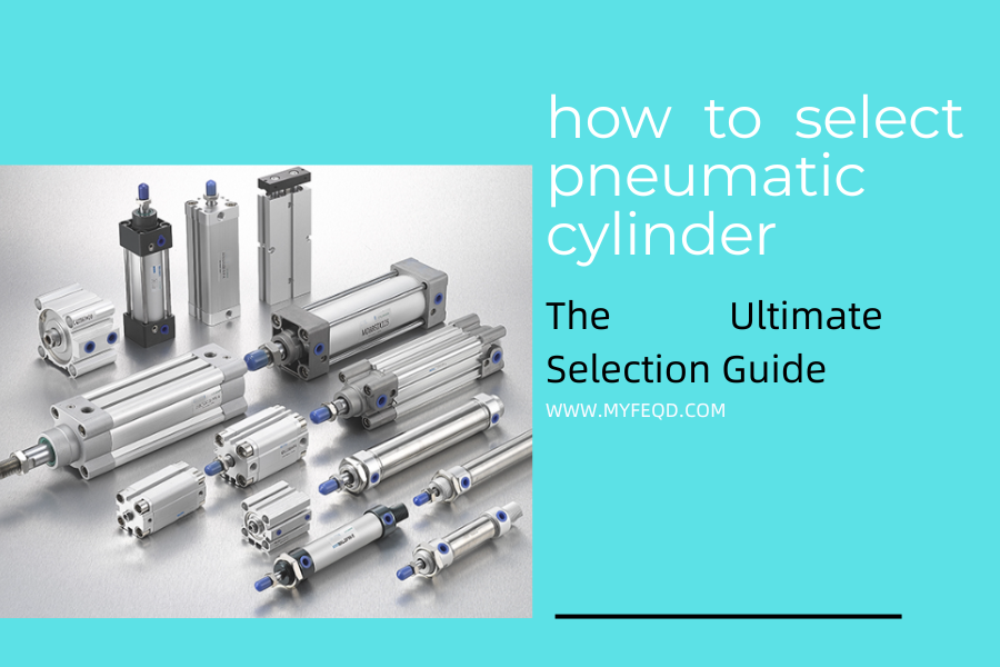
how to select pneumatic cylinder
The pneumatic cylinder serves as the very soul—the core component—of any pneumatic system. Classified as an actuator, its fundamental function is to convert the pressure energy of compressed air into mechanical energy, thereby driving equipment to execute linear reciprocating motion or rotational oscillation.
These cylinders are widely utilized across a diverse range of industries, including automated production lines, machine tools, construction machinery, electronic equipment, food processing, and packaging machinery.
The quality of the cylinder and the appropriateness of its selection directly determine the operational stability, efficiency, and service life of the associated equipment; furthermore, they can significantly impact the energy consumption and maintenance costs of the entire pneumatic system.
Consequently, it is paramount to master the proper methods for purchasing cylinders—specifically, by avoiding common selection pitfalls and choosing products that are optimally suited to one’s specific operating conditions.
This article outlines key selection parameters, industry-specific recommendations, and strategies for avoiding common errors. Serving as the ultimate purchasing guide for pneumatic cylinders, it aims to empower users to quickly and confidently select the right cylinder for their needs.
When purchasing pneumatic cylinders, the first priority is to mitigate fundamental risks.
1. The manufacturing process and material selection of a cylinder directly determine its durability and performance stability; therefore, the first step when making a purchase is to carefully vet the manufacturer.
By scrutinizing the company’s organizational structure, factory environment, quality control protocols, and after-sales procedures, one can effectively avoid issues such as cylinder jamming, leakage, and premature failure caused by inferior materials or shoddy workmanship.
2.The manufacturing standards applied to a pneumatic cylinder directly determine its compatibility, interchangeability, and safety; therefore, when making a purchase, it is crucial to carefully verify the specific standards adopted by the manufacturer during production.
Prioritizing products that adhere to industry-benchmark technical standards—such as those set by SMC, AirTAC, Festo, Norgren, and Parker—ensures high universality, thereby facilitating easier spare parts replacement and maintenance in the future.
3.The performance of a pneumatic cylinder directly determines its operational reliability; therefore, during the purchasing process, a comprehensive on-site inspection of the cylinder’s external appearance, internal and external leakage, and no-load performance is required. The specific requirements are as follows:
- Appearance: The inner and outer walls of the pneumatic cylinder barrel, as well as the surface of the piston rod, must be smooth and even, free from defects such as scratches, dents, or corrosion, to prevent accelerated wear of seals—and the consequent risk of leakage—caused by surface damage.The junctions between the end caps and the cylinder body must be free of pores, sand holes, and cracks; weld seams must be smooth and uniform to ensure the cylinder’s sealing integrity and structural strength.The surface coating of the cylinder must be applied evenly, without peeling or flaking; it must possess excellent rust-proofing and corrosion-resistant properties to ensure suitability for various operating environments.
- Internal and External Leakage Detection: Leakage is a common fault in pneumatic cylinders and a critical factor affecting the pressure stability of pneumatic systems; therefore, leakage levels must be strictly controlled. Standard Requirements: With the exception of the rod end, no external leakage is permitted in any other part of the cylinder. Internal leakage (leakage between the cylinder barrel and the piston) must be ≤ (3 + 0.15D) ml/min (where D is the cylinder bore diameter, in mm). External leakage at the rod end (leakage between the piston rod and the seals) must be ≤ (3 + 0.15d) ml/min (where d is the piston rod diameter, in mm). When purchasing, customers may request that the manufacturer perform a simple on-site test (by applying air at the rated pressure and observing for any audible signs of leakage or visible traces of air escape).
- No-Load Performance Testing: No-load performance directly reflects the operational smoothness of a cylinder, making it particularly relevant for applications requiring high operational precision (such as precision positioning and small-scale automation equipment). Place the cylinder in a no-load state, introduce compressed air to initiate low-speed operation, and observe whether any “crawling” or “jittering” phenomena occur. The lower the operating speed at which the cylinder remains free of crawling, the superior its no-load performance; this indicates smoother operation and effectively prevents issues such as stalling or positioning deviations during equipment operation.
- The pressure resistance of a pneumatic cylinder (it must be capable of withstanding 1.25 times its rated pressure without leakage or deformation) and its cushioning performance (the end-cushioning mechanism must be responsive to prevent severe impact when the cylinder reaches the end of its stroke, thereby avoiding damage to both the equipment and the cylinder itself). The mounting configuration and dimensions of a pneumatic cylinder directly determine whether it is compatible with existing equipment and installation sites. When making a selection, it is essential to verify the available installation space and mounting method in advance to avoid installation-related issues.
- Mounting Styles for Pneumatic Cylinders: These include fixed mounting, CA rear-cover mounting (single-clevis type), CB rear-cover mounting (double-clevis type), FA front-cover mounting (front flange), FB rear-cover mounting (rear flange), LB foot mounting, TC trunnion mounting, and TC-M trunnion mounting with a base. The appropriate mounting style must be selected based on the equipment’s installation location and motion trajectory to ensure that the cylinder operates without interference and is subjected to uniform loading.
- Verify Installation Dimensions: The installation dimensions of the pneumatic cylinder—such as bore diameter, stroke length, mounting hole spacing, and piston rod length—must precisely match the dimensions reserved on the equipment. If specific non-standard dimensions are required, custom orders can be placed with the manufacturer; however, please note that most pneumatic cylinders are not kept in stock. Custom-made cylinders typically entail a longer lead time (usually 7–15 days), which may impact the installation schedule.
Therefore, it is highly recommended to utilize standard-model pneumatic cylinders whenever possible. Standard models not only offer shorter lead times (typically 1–3 days) but also facilitate easier replacement and maintenance in the future; furthermore, their components possess high interchangeability, thereby helping to reduce overall maintenance costs.
Cylinder Types and Applicable Scenarios
There is a wide variety of cylinder types; different types feature distinct structures and functions, and are suited to varying operating conditions.
Drawing upon the selection parameters discussed previously, we provide a brief overview of the various cylinder types available. This aims to help you quickly identify the best match for your specific requirements, thereby avoiding the pitfall where the “parameters are correct, but the cylinder type is wrong.”
1.Standard Cylinder: The most widely used series type. Fundamentally designed to execute linear reciprocating motion, they are categorized into two types—single-acting and double-acting—and are suitable for the vast majority of applications.
- Single-Acting Cylinders: Pressurized at only one end, they rely on a spring for retraction. Featuring a simple structure and low cost, they are ideal for scenarios involving short strokes and unidirectional force requirements (e.g., pushing materials on automated production lines or clamping workpieces in small-scale equipment).
- Double-Acting Cylinders: Pressurized alternately at both ends to achieve bidirectional movement. They deliver consistent thrust and pull forces, operate smoothly, and are well-suited for applications involving long strokes and bidirectional force requirements (e.g., lifting, material handling, and reciprocating feeding).
Note: Standard cylinders are available in the following model series: SC, SU, SI, MBB, CA2, etc.
2.The mini cylinder is a compact, lightweight, and cylindrical pneumatic cylinder widely utilized in automated equipment where space is limited. It is currently one of the most widely used series of mini cylinders within the field of industrial automation.
This category includes models such as MA, MAL, CM2, MF, C85, MI, CG1, MG, and others.
3.Thin-Type Cylinders: Featuring a compact structure and low profile, these cylinders are suitable for applications with extremely limited installation space (such as within small-scale equipment or precision instruments).
They are designed for lighter loads and shorter strokes, and are commonly found in electronic devices and medical equipment.
4.twin-rod cylinder is a pneumatic actuator featuring two parallel piston rods. Compared to single-rod cylinders, it offers superior resistance to torsion and higher guiding precision, making it widely applicable in scenarios requiring stable linear motion and the capacity to withstand lateral loads.
5.three-axis cylinder is a high-precision pneumatic actuator based on a dual-axis cylinder, enhanced by the addition of a third guide rod. It features exceptional resistance to torsion, extremely high guiding precision, and superior load-bearing capabilities, making it a core actuating component in precision automation equipment.
6.rotary cylinder is a pneumatic actuator that converts the linear motion of compressed air into rotational motion.
It is capable of executing precise oscillating or flipping movements within a specific angular range, and is widely utilized in applications requiring angular positioning, workpiece flipping, and valve opening or closing.
7. guided cylinder is a high-precision pneumatic actuator that integrates a guiding mechanism into a standard cylinder design. Utilizing a structure comprising either four guide rods or two guide rods paired with a slider, it facilitates linear motion characterized by high rigidity, high precision, and high load-bearing capacity, serving as a core component in precision automation equipment.
8. slide cylinder is a high-precision pneumatic actuator that integrates a linear guide and a pneumatic cylinder into a single unit. Utilizing precision ball guides or crossed-roller guides, it achieves linear motion characterized by ultra-low friction and exceptional precision, making it the preferred solution for applications involving precision positioning, material handling, and inspection.
9.rodless cylinder is a specialized pneumatic actuator characterized by the absence of a piston rod extending outside the cylinder body. By utilizing either magnetic coupling or mechanical linkage between an internal piston and an external slider, it converts the pressure energy of compressed air into linear motion; it is particularly well-suited for applications involving long strokes, limited space, or requirements for anti-rotation.
10.finger cylinder is a type of pneumatic actuator specifically designed for gripping, clamping, and handling workpieces. It utilizes a cylinder to drive two (or three) fingers in a relative motion, thereby enabling the clamping or releasing of a workpiece; it serves as a core component of End-of-Arm Tooling (EOAT) in industrial automation.
11.stopper cylinder is a pneumatic actuator specifically designed to block, position, halt, or secure workpieces or pallets. By utilizing the vertical lifting and lowering motion of its piston rod (or stopper block), it enables the controlled stopping or releasing of workpieces on a conveyor line; as such, it serves as a critical control component within automated conveying systems—such as double-speed chain conveyors, roller conveyors, and pallet lines.
12.pressure booster cylinder is a pneumatic-hydraulic or pneumatic-pneumatic conversion device that transforms low-pressure compressed air into high-pressure hydraulic fluid or high-pressure air. It utilizes the mechanical principle of a large-area piston driving a small-area piston to achieve pressure amplification, and is widely employed in applications requiring localized high pressure without the need for a complete hydraulic system.
Note: In addition to the cylinder series outlined above, we have other series currently under development and design; furthermore, non-standard cylinders can also be fully customized to your specifications.
If you have specific requirements, please contact us for custom development; we possess a professional technical team and years of manufacturing experience. Wenzhou Maifeng Pneumatic Co., Ltd. (MYFEQD) is a partner worthy of your trust.
Pneumatic Cylinder Selection Parameters
1.Cylinder Bore Diameter (Determines Cylinder Output Force)
The bore diameter is a core parameter of a cylinder, directly determining the maximum thrust and pull forces the cylinder can generate. The calculation formulas are as follows: Thrust F1 = P × π × D²/4, and Pull F2 = P × π × (D² – d²)/4 (where P represents the rated operating pressure in MPa; D represents the bore diameter; and d represents the piston rod diameter).
When making a selection, it is necessary to calculate the minimum required cylinder bore based on the load magnitude and operating pressure, and then incorporate a safety margin of 10% to 20% to accommodate load fluctuations and pressure variations.
This approach prevents the selection of an undersized bore—which would result in insufficient thrust and an inability to drive the load—while also avoiding an oversized bore, which would increase compressed air consumption, raise energy costs, and occupy excessive installation space.
Specific Operating Condition Calculation Examples (2 Practical Scenarios—Directly Applicable):
Case Study 1: Automated Production Line Feeding Application (Horizontal mounting, no inclination, stable load) Given Conditions: Feeding load F = 500 N; Pneumatic system rated operating pressure P = 0.5 MPa (5 bar); Single-acting cylinder (only thrust calculation required); 15% safety margin included.
Calculation Steps: 1. First, calculate the minimum required thrust: F_min = F ÷ (1 – Margin) = 500 N ÷ 0.85 ≈ 588.2 N. 2. Substitute this value into the thrust formula F1 = P × π × D²/4, and rearrange the equation to solve for D: D = √(4 × F_min ÷ (P × π)). 3. Substitute the numerical values (where P = 0.5 MPa = 5 × 10⁵ Pa): D = √(4 × 588.2 ÷ (5 × 10⁵ × 3.14)) ≈ √(2352.8 ÷ 1,570,000) ≈ √0.001498 ≈ 0.0387 m = 38.7 mm. 4. Based on industry-standard cylinder bore sizes (common standard bores include 32 mm, 40 mm, and 50 mm), select a 40 mm bore (which is larger than 38.7 mm and satisfies the requirements after accounting for the safety margin).
Case Study 2: Small-Scale Mechanical Lifting Application (Vertically mounted; requires overcoming gravity; load exhibits slight fluctuations) Given Conditions: Lifting load F = 800 N (including workpiece weight); pneumatic system rated operating pressure P = 0.6 MPa (6 bar); double-acting cylinder (calculation based on pulling force; piston rod diameter d = 12 mm); 20% safety margin reserved.
Calculation Steps: 1. Required Minimum Pulling Force: F_min = F ÷ (1 – Margin) = 800 N ÷ 0.8 ≈ 1000 N; 2. Substitute into the pulling force formula F₂ = P × π × (D² – d²) / 4, and rearrange to solve for D: D = √((4 × F_min ÷ (P × π)) + d²); 3. Substitute the numerical values (P = 0.6 MPa = 6 × 10⁵ Pa, d = 12 mm = 0.012 m): D = √((4 × 1000 ÷ (6 × 10⁵ × 3.14)) + 0.012²) ≈ √(4000 ÷ 1,884,000 + 0.000144) ≈ √(0.002123 + 0.000144) ≈ √0.002267 ≈ 0.0476 m = 47.6 mm; 4. Select a standard bore diameter of 50 mm, which satisfies the lifting requirements and accommodates load fluctuations.
Supplementary Note: When performing calculations, ensure unit consistency (convert pressure units to Pa and length units to m). If operating conditions involve factors such as impact or inclination, the safety margin may be appropriately increased to 20%–30% to ensure sufficient cylinder output force.
2.Pneumatic Cylinder Stroke (Determines the Cylinder's Range of Motion)
The stroke refers to the maximum extension distance of the cylinder’s piston rod. The required stroke length must be determined based on the specific motion requirements of the equipment; additionally, a margin of 5–10 mm should be reserved to prevent the equipment from failing to reach its designated position due to an insufficient stroke, or from wasting space and experiencing operational instability due to an excessively long stroke.
Note: The longer the stroke, the lower the rigidity of the cylinder, making it prone to vibration and bending during operation. If a long-stroke cylinder is required, it is recommended to select a model equipped with guide rods to enhance operational stability.
3.Pneumatic Cylinder Operating Pressure
The rated operating pressure of the pneumatic cylinder must align with the operating pressure of the pneumatic system. Common rated operating pressures range from 0.4 to 0.6 MPa; therefore, when making a selection, it is essential to verify the system pressure to prevent mismatches that could result in insufficient cylinder output force or abnormal operating speeds.
If the system pressure is subject to significant fluctuations, a cylinder with superior pressure resistance should be selected to ensure proper operation—free from leaks or damage—within the full range of pressure variations.
4.Pneumatic Cylinder Operating Speed
The operating speed of a pneumatic cylinder typically ranges from 50 to 500 mm/s; the appropriate speed should be selected based on the specific operational requirements of the equipment:
For applications requiring precise positioning and smooth operation (such as electronic component assembly), a low speed (50–200 mm/s) is recommended. For applications demanding rapid movement and high production efficiency (such as packaging machinery), a high speed (200–500 mm/s) is recommended.
Note: Excessive operating speed increases the impact force on the cylinder, thereby shortening its service life; conversely, a speed that is too slow will compromise production efficiency. The cylinder’s operating speed can be fine-tuned by adjusting the flow control valves within the pneumatic system.
5.Operating Environment (Determines the Material of the Pneumatic Cylinder)
- Standard Environments: A pneumatic cylinder made of conventional anodized aluminum alloy is sufficient. It features a carbon steel piston rod and painted iron end caps.
- For applications involving humid, corrosive, or high-temperature environments—as well as food production settings—pneumatic cylinders constructed from stainless steel and featuring fluororubber seals should be selected to prevent cylinder corrosion and seal damage.
Summarize
The core logic behind selecting a pneumatic cylinder is as follows: first, clearly define your specific operating conditions (determining the required actuation type, load, speed, pressure, environmental factors, and mounting requirements);
Next, match these needs to the key technical parameters (bore size, stroke length, and mounting style); finally, identify reputable manufacturers, verify product standards and performance specifications, and avoid common pitfalls.
A high-quality pneumatic cylinder not only ensures the stable operation of your equipment but also reduces energy consumption and long-term maintenance costs, thereby extending the overall service life of the machinery.
If you are unsure about the appropriate selection solution for your specific operating conditions, you can provide detailed operational parameters (such as load magnitude, working pressure, and available mounting space) to consult with the manufacturer’s technical experts and obtain precise selection recommendations.
Additionally, performing regular maintenance on the cylinder—including cleaning, lubrication, and inspecting seals—can further extend its service life.
For more information regarding pneumatic cylinders, please contact us.