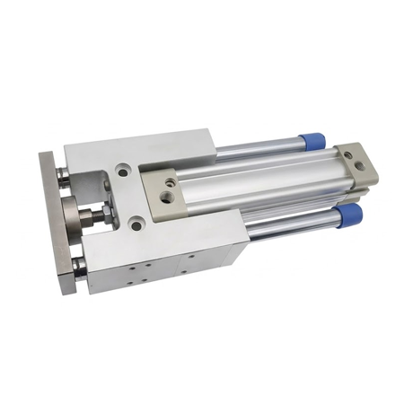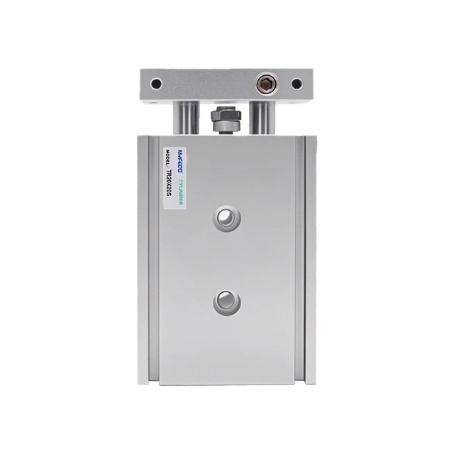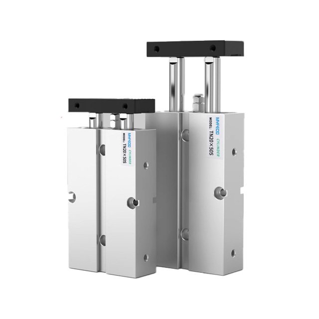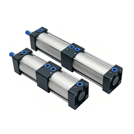
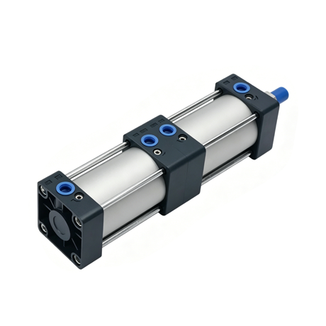
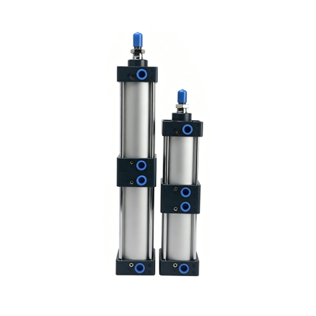
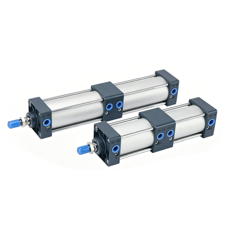
The SCT cylinder is an AirTAC-standard, double-acting, multi-position cylinder (also commonly referred to as the SUT dual-stroke or booster cylinder).
It consists of two SC standard cylinders connected in series, enabling a two-stage stroke and multiple positioning points.
Features:
Product Technical Specifications
| Bore diameter (mm) | 32 | 40 | 50 | 63 | 80 | 100 |
| Action Form | Double-acting, Multi-position Type | |||||
| Working Medium | Clean air (filtered through a screen with a mesh size of 40 µm or larger) | |||||
| Fixed Installation Configuration | FA,FB,CA,B,LB | |||||
| Operating Pressure Range | 0.15~1.0Mpa(22~145Psi)(1.5~10.0bar) | |||||
| Guaranteed Pressure Resistance | 1.5Mpa(215psi)(15bar) | |||||
| Operating Temperature Range | -20°C~70°C (Sealing materials are customizable and replaceable, with an operating temperature range extending up to +250°C.) | |||||
| Operating Speed Range | 30~800 mm/s | |||||
| Travel Tolerance Range | (0~250 +1.0)(250~1000 +1.5)(1001~1500 +2.0) | |||||
| Buffering Form | Adjustable Cushioning (Air Cushioning) | |||||
| Cushion Stroke | 21mm | 28mm | 29mm | |||
| Connection Thread Diameter | PT1/8 | PT1/4 | PT3/8 | PT1/2 | ||
| Piston Rod Connection Accessories | I: I-Type Joint U: Fish-Eye Joint Y: Y-Type Joint F: Floating Joint | |||||
| Compatible with Magnetic Switches | CS1-G ,DMSG,CS1-U,CS1-F, | |||||
Note: Connecting pipe threads are available in NPT and G thread options.
Standard Travel Range
| Bore diameter (mm) | Standard Travel Stroke(mm) | Maximum Travel | Permissible Travel |
| 32 | 25.50.75.80.100.125.150.160.175.200.250.300.350.400.450.500 | 500 | 800 |
| 40 | |||
| 50 | |||
| 63 | |||
| 80 | |||
| 100 |
Note: If the stroke is ≥ 800 mm, it will be treated as a non-standard item. For other special stroke lengths, please contact Wenzhou Maifeng Pneumatic Co., Ltd. (MYFEQD).
Cylinder Theoretical Output Table (Unit: N)
The force output chart for pneumatic cylinders constitutes one of the critical elements in the cylinder selection process, enabling the calculation of the required load force.
Multiplying the output force of a pneumatic cylinder by a factor of 0.5 to 0.7 yields the cylinder’s effective load force.
| Bore diameter (mm) | Piston Rod Outer Diameter | Mode of Action | Compression Area(mm²) | 0.1Mpa | 0.2Mpa | 0.3Mpa | 0.4Mpa | 0.5Mpa | 0.6Mpa | 0.7Mpa | 0.8Mpa | 0.9Mpa | |
| 32 | 12 | Double-acting type | Load Testing | 804 | 160.08 | 321.6 | 482.4 | 643.2 | 804 | 964.8 | 1125.6 | 1286.4 | 1447.2 |
| Tensile Testing | 690 | 138 | 276 | 414 | 552 | 690 | 828 | 966 | 1104 | 1242 | |||
| 40 | 16 | Load Testing | 1256 | 251.2 | 502.4 | 753.6 | 1004.8 | 1256 | 1507.2 | 1758.4 | 2009.6 | 2260.8 | |
| Tensile Testing | 1055 | 211 | 422 | 633 | 844 | 1055 | 1266 | 1477 | 1688 | 1899 | |||
| 50 | 20 | Load Testing | 1963 | 392.6 | 785.2 | 1177.8 | 1570.4 | 1963 | 2355.6 | 2748.2 | 3140.8 | 3533.4 | |
| Tensile Testing | 1649 | 329.8 | 659.6 | 989.4 | 1319.2 | 1649 | 1978.8 | 2308.6 | 2638.4 | 2968.2 | |||
| 63 | 20 | Load Testing | 3117 | 623.4 | 1246.8 | 1870.2 | 2493.6 | 3117 | 3740.4 | 4363.8 | 4987.2 | 5610.6 | |
| Tensile Testing | 2803 | 560.6 | 1121.2 | 1681.8 | 2242.4 | 2803 | 3363.6 | 3924.2 | 4484.8 | 5045.4 | |||
| 80 | 25 | Load Testing | 5026 | 1005.2 | 2010.4 | 3015.6 | 4020.8 | 5026 | 6031.2 | 7036.4 | 8041.6 | 9046.8 | |
| Tensile Testing | 4536 | 907.2 | 1814.4 | 2721.6 | 3628.8 | 4536 | 5443.2 | 6350.4 | 7257.6 | 8164.8 | |||
| 100 | 25 | Load Testing | 7853 | 1570.6 | 3141.2 | 4711.8 | 6282.4 | 7853 | 9423.6 | 10994.2 | 1256.8 | 14135.4 | |
| Tensile Testing | 7362 | 1472.4 | 2944.8 | 4417.2 | 5889.6 | 7362 | 8834.4 | 10306.8 | 11779.2 | 13251.6 | |||
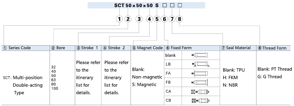
Finished Product Order Code
Materials of Main Components
SCT/SUT series Multi-Position Pneumatic Cylinders
| Spare Part Name | Material | Spare Part Name | Material |
| Nut | Carbon Steel | magnet | Plastic Parts |
| Piston Rod | 45# Steel Hard Chrome-Plated and Ground Rod | Buffer O-ring | NBR |
| Front Cover O-ring | TPU | Pipe Wall O-ring | NBR |
| Bushing | Wear-resistant materials | Connection Base | Aluminum Alloy |
| Front Cover | Aluminum Alloy | Piston | Aluminum Alloy |
| Buffer Seal | TPU | Hex Socket Screw | Carbon Steel |
| Cylinder Block | Aluminum Alloy Profiles | Back Cover | Aluminum Alloy |
| O-ring | NBR | Pillar | Carbon Steel |
| Piston O-ring | NBR | Pillar Nut | Carbon Steel |
| Wear Pad | Wear-resistant materials |
Product size information
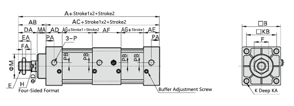
| Bore / Symbol | A | AB | AC | AD | AE | AF | AG | B | D | DA | E | EA | F | FA | H | K | KA | KB | M | MA | P | PA | PB |
| 32 | 233 | 47 | 186 | 27.5 | 27.5 | 55 | 38 | 45 | 12 | 32 | M10*1.25 | 22 | 17 | 6 | 10 | M6*1.0 | 14.5 | 33 | 28 | 15 | PT1/8 | 14 | 5.5 |
| 40 | 235 | 49 | 186 | 27.5 | 27.5 | 55 | 38 | 50 | 16 | 34 | M12*1.25 | 24 | 17 | 7 | 13 | M6*1.0 | 14.5 | 37 | 32 | 15 | PT1/4 | 15 | 6 |
| 50 | 243 | 57 | 186 | 27.5 | 27.5 | 55 | 38 | 62 | 20 | 42 | M16*1.5 | 32 | 23 | 8 | 17 | M6*1.0 | 14.5 | 47 | 38 | 15 | PT1/4 | 17 | 8.5 |
| 63 | 249 | 57 | 192 | 27.5 | 27.5 | 55 | 41 | 75 | 20 | 42 | M16*1.5 | 32 | 23 | 8 | 17 | M8*1.25 | 14.5 | 56 | 38 | 15 | PT3/8 | 15 | 9.5 |
| 80 | 296 | 75 | 221 | 33 | 33 | 73 | 41 | 94 | 25 | 54 | M20*1.5 | 40 | 26 | 10 | 22 | M10*1.5 | 17 | 70 | 47 | 21 | PT3/8 | 19.5 | 10 |
| 100 | 308 | 75 | 233 | 33 | 33 | 73 | 47 | 112 | 25 | 54 | M20*1.5 | 40 | 26 | 10 | 22 | M10*1.5 | 17 | 84 | 47 | 21 | PT1/2 | 16.5 | 11 |
In addition to the information regarding cylinders provided above, the following related details should also be reviewed.