Compártelo con tus amigos:
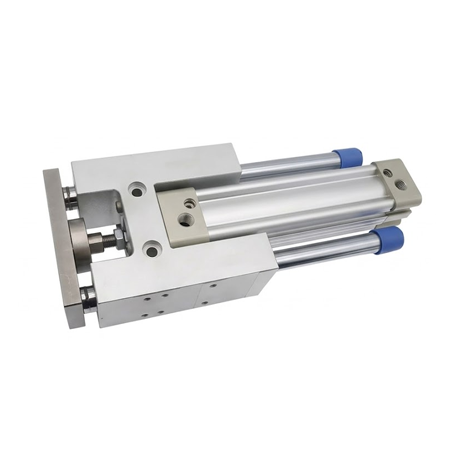
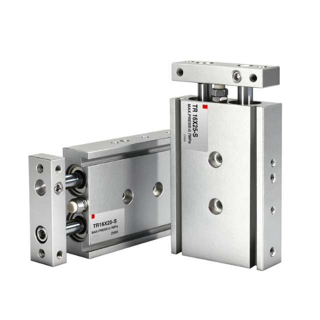
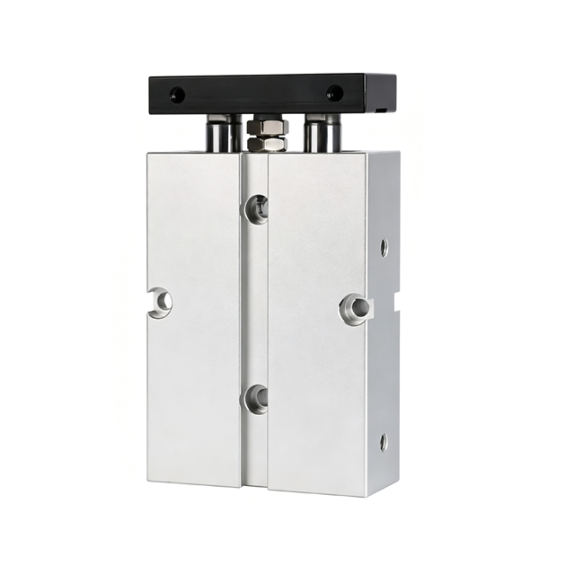
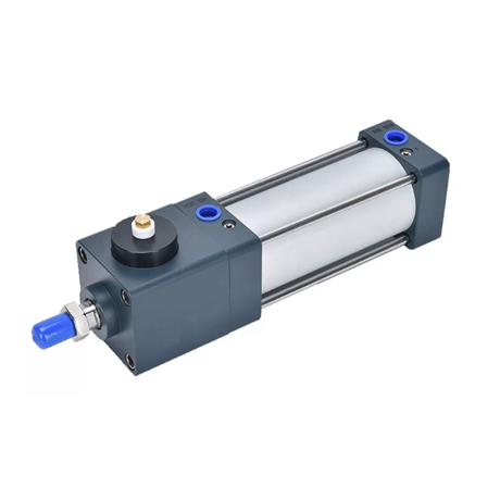
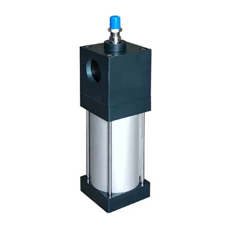
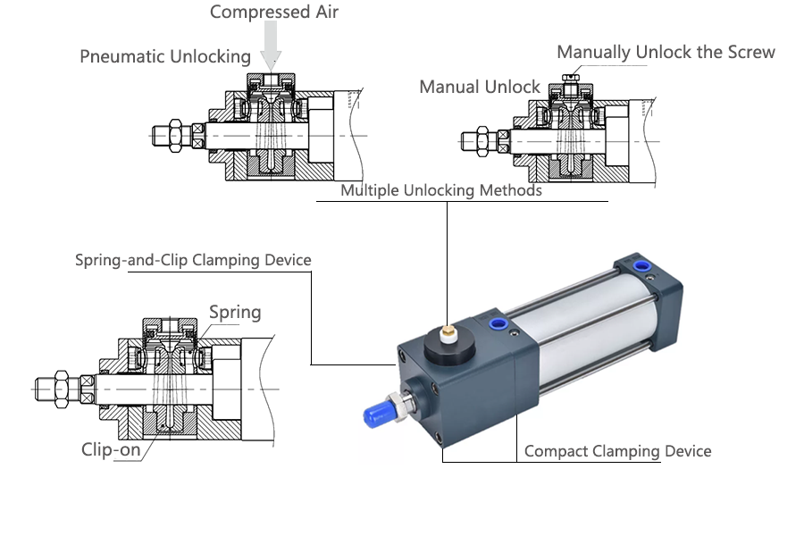
The BSC Series Clamping Cylinder is a pneumatic cylinder assembly comprising an aluminum alloy cylinder barrel and end caps, a #45 high-carbon steel piston rod, and a compact clamping mechanism.
It offers various unlocking methods, including pneumatic unlocking and manual unlocking.
The structure is simple, locking and unlocking are rapid and effective, and state switching is stable.
The clamping mechanism is highly integrated and occupies no additional space.
Detailed technical specifications and parameters for this pneumatic cylinder are provided below.
BSC Series Clamping Cylinder Structure
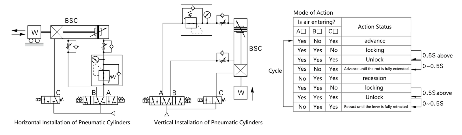
Installation and Usage
Technical Parameters
| Inner diameter mm (bore diameter) | 32 | 40 | 50 | 63 | 80 | 100 | 125 | |
| Action Form | Double-acting type | |||||||
| Working Medium | Air (filtered through a 40 µm mesh screen) | |||||||
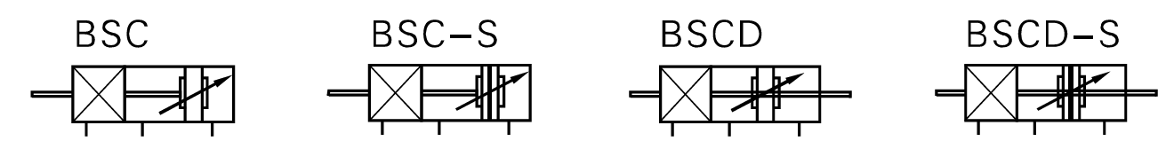
| Fixed Form | BSC | Basic Type FA, FB, CA, CB, LB, TC, TCM1 | ||||||
| BSCD | Basic Type FA, LB, TC, TCM1 | |||||||
| Operating Pressure Range | 0.15~0.7Mpa(22~100Psi)(1.5~7.0bar) | |||||||
| Guaranteed Pressure Resistance | 1.5Mpa(215Psi)(15bar) | |||||||
| Operating Temperature | -20°C~70°C | |||||||
| Operating Speed Range | 30~800mm/s | 30~500mm/s | ||||||
| Travel Range | (0~250 +1.0)(250~1000 +1.5)(1001~1500 +2.0) | |||||||
| Buffering Form | Adjustable Cushioning (Air Cushioning) | |||||||
| Cushion Stroke (mm) | 21 | 28 | 29 | 28 | ||||
| Interface Thread Diameter | Pneumatic Cylinder Section | PT1/8 | PT1/4 | PT3/8 | PT1/2 | |||
| Clamping Mechanism Section | G1/8 | |||||||
| Unlock Stress | 0.3~0.7Mpa(45~100psi)(3~7bar) | |||||||
| Static Holding Force (N) | 600 | 900 | 1400 | 2200 | 3600 | 5500 | 8600 | |
| Piston Rod Connection Accessories | I: I-Type Joint U: Fish-Eye Joint Y: Y-Type Joint F: Floating Joint | |||||||
| Compatible with Magnetic Switches | SC1-U SC1-F CS1-G D-A93 D-M9B D-273 D-M9N DS1-E DMSH CS-9D CS-8G DFSH DFSE | |||||||
Note: Interface threads are available in PT and G options.
BSC Series Clamping Cylinder Standard Travel Stroke
| Inner diameter mm (bore diameter) | Standard Travel Stroke(mm) | Maximum Stroke |
| 32 | 25.50.75.80.100.125.150.160.175.200.250.300.350.400.450.500 | 700 |
| 40 | 25.50.75.80.100.125.150.160.175.200.250.300.350.400.450.500.600.700.800 | 800 |
| 50 | 25.50.75.80.100.125.150.160.175.200.250.300.350.400.450.500.600.700.800.900.1000 | 1000 |
| 63 | ||
| 80 | ||
| 100 | ||
| 125 |
Note: For other special stroke lengths, please contact our company.
For the output force data of this pneumatic cylinder model, please refer to the output force table for the SC series pneumatic cylinders.
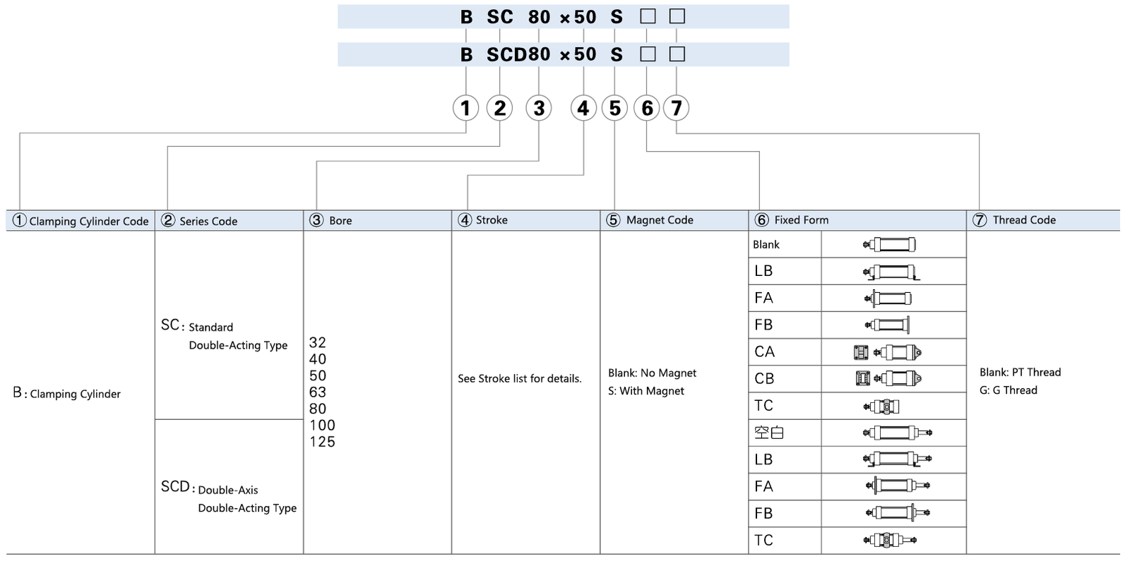
BSC Series Clamping Cylinder Finished Product Order Code
Size Information
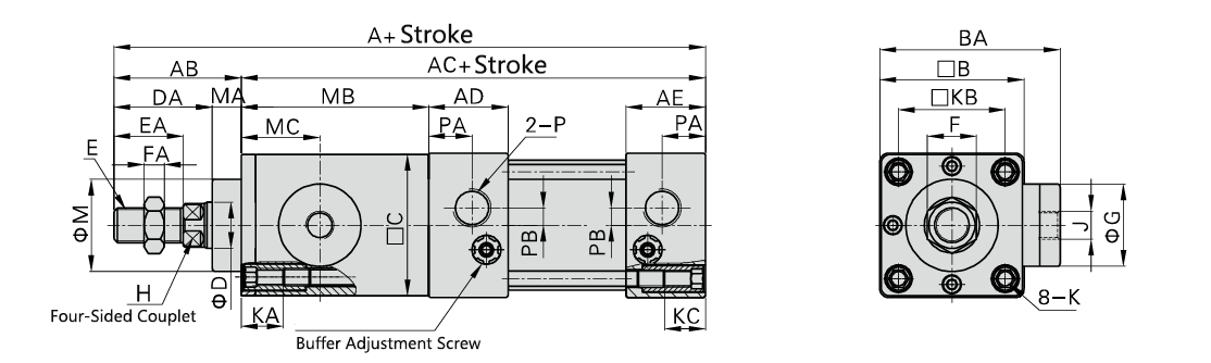
| Bore / Symbol | A | AB | CA | AD | AE | B | BA | C | D | DA | E | EA | F | FA | G | H | J | K | KA | KB | KC | M | MA | MB | MC | P | PA | PB |
| 32 | 195 | 42 | 153 | 27.5 | 27.5 | 45 | 64 | 44 | 12 | 32 | M10*1.25 | 22 | 17 | 6 | 30 | 10 | G1/8 | M6*1.0 | 14.5 | 33 | 14 | 28 | 10 | 60 | 25 | PT1/8 | 14 | 5.5 |
| 40 | 202 | 44 | 158 | 27.5 | 27.5 | 50 | 71.5 | 49 | 16 | 34 | M12*1.25 | 24 | 17 | 7 | 36.5 | 13 | G1/8 | M6*1.0 | 14.5 | 37 | 14 | 32 | 10 | 65 | 27.5 | PT1/4 | 15 | 6 |
| 50 | 221 | 52 | 169 | 27.5 | 27.5 | 62 | 82 | 61 | 20 | 42 | M16*1.5 | 32 | 23 | 8 | 44.5 | 17 | G1/8 | M6*1.0 | 14.5 | 47 | 14 | 38 | 10 | 76 | 33 | PT1/4 | 17 | 8.5 |
| 63 | 224 | 52 | 172 | 27.5 | 27.5 | 75 | 88 | 73.5 | 20 | 42 | M16*1.5 | 32 | 23 | 8 | 44.5 | 17 | G1/8 | M8*1.25 | 14.5 | 56 | 14 | 38 | 10 | 76 | 33 | PT3/8 | 15 | 9.5 |
| 80 | 285 | 69 | 216 | 33 | 33 | 94 | 107 | 92.5 | 25 | 54 | M20*1.5 | 40 | 26 | 10 | 55.5 | 22 | G1/8 | M10*1.5 | 17 | 70 | 16 | 47 | 15 | 109 | 47 | PT3/8 | 19.5 | 10 |
| 100 | 291 | 69 | 222 | 33 | 33 | 112 | 116 | 110.5 | 25 | 54 | M20*1.5 | 40 | 26 | 10 | 55.5 | 22 | G1/8 | M10*1.5 | 17 | 84 | 16 | 47 | 15 | 109 | 47 | PT1/2 | 16.5 | 11 |
| 125 | 321 | 86 | 235 | 38 | 38 | 136 | 150 | 133 | 32 | 68 | M27*2 | 54 | 41 | 13.5 | 70 | 27 | G1/8 | M12*1.75 | 21.5 | 104 | 16 | 52 | 18 | 120 | 63 | PT1/2 | 20 | 14 |
Note: BSC Series Clamping Cylinder Size Information The dimensions of the magnetic and non-magnetic versions are identical.
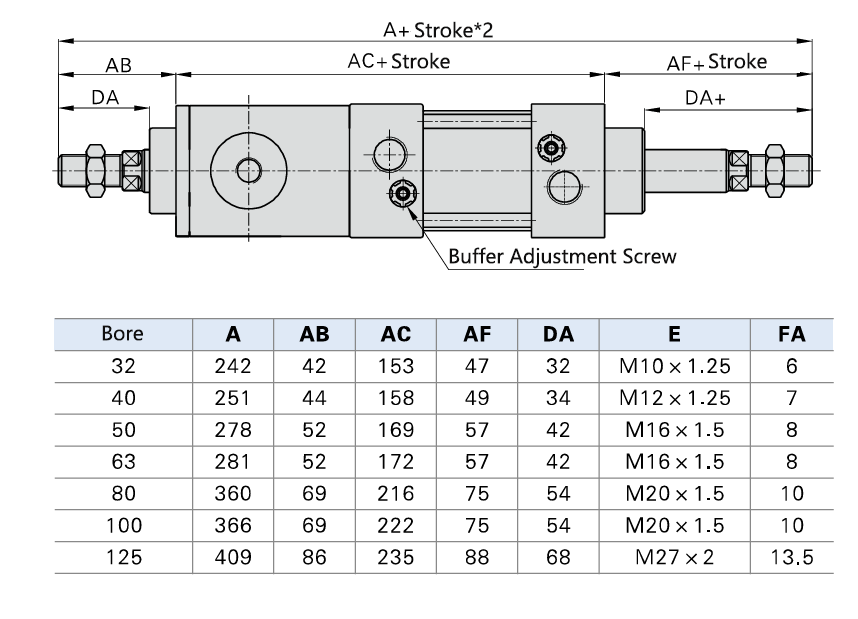
Note: BSCD Series Clamping Cylinder Size Information
In addition to the information regarding cylinders provided above, the following related details should also be reviewed.
Envíenos
Fabricantes de neumáticos en China