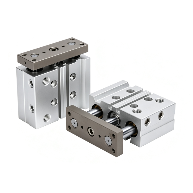
Guide Rod Cylinder

1. Exceptional torsional and rotational resistance: Dual guide rods constrain the unit, preventing piston rod rotation and maintaining a fixed output orientation—ideal for workstations requiring constant angular positioning.
2. High radial and lateral load capacity: Capable of withstanding significant side loads without the need for additional external guiding mechanisms, thereby saving installation space.
3. High precision: Minimal clearance between guide rods and bearings results in superior repeatability compared to standard single-rod cylinders.
4. Compact design: Guiding components and the cylinder are integrated into a single unit, simplifying assembly.

Why Choose Us

Built on precision,
delivered with advantage.

01

OEM / ODM

20 years of experience in the manufacturing industry, delivering custom solutions tailored to your exact specifications and production requirements.

20+ Years Experience
02

Strict Technical Standards

The quality we deliver rivals that of major brands, as we strictly adhere to the technical standards of leading domestic and international labels.

ISO-Aligned Quality
03

Great Price

Located in Liushi, Yueqing, Wenzhou, Zhejiang Province, China, our company boasts a comprehensive product component supply chain, advanced high-end equipment, and a long-standing manufacturing heritage.

Direct Factory Pricing
MYFEQD — Precision Pneumatic Components

High output force

Guide Rod Cylinder: Basic Parameters for Selection

guided cylinder—also known as a three-shaft cylinder—is an integrated cylinder unit featuring three rigid guide shafts.

It consists of a piston rod, two parallel guide rods, a front flange, a cylinder barrel, a piston, and an optional magnetic ring.

As the piston moves, the two guide rods slide synchronously, providing resistance against rotation and off-center loads.

TCL TCM Series guide rod pneumatic cylinder 1

TCM/TCL Series Guided Cylinders

Complies with JIS standards

1. Complies with JIS standards;
2. Features two guide rods made of special bearing steel, guided by either linear ball bearings or brass sliding bearings, offering high resistance to torsional and lateral loads. Note: Linear ball bearings are suitable for lifting applications or scenarios requiring high precision and load capacity, particularly where low-friction movement is essential; brass sliding bearings are suitable for applications involving radial loads (such as braking), offering more than double the lateral impact resistance of standard brake cylinders and superior torsional rigidity;
3. The drive and guide units are integrated into a single body, eliminating the need for extra accessories and minimizing space requirements; selectable air ports allow for convenient installation;
4. Precision positioning holes are provided on the bottom and rear faces of the body as well as on the mounting plate (see the “PA” and “XX” holes in the dimensional drawing), enabling high-precision mounting for demanding applications;
5. Four sensor slots on the body accommodate various sensor mounting configurations;
6. The body’s unique design supports mounting and fixation from multiple directions.
Bore Size (Inner Diameter mm)610121620253240506380100
Action TypeDouble Acting
Working MediumAir (filtered through 40μm or above filter)
Working Temperature-20°C ~ +70°C
Operating Pressure Range0.2~0.7MPa0.15~1.0MPa
Proof Pressure1.2MPa1.5MPa
Operating Speed Range50~500mm/s30~500mm/s50~400mm/s
CushioningAnti-collision pad
Non-rotating Accuracy (linear bearing)—±0.08°±0.07°±0.06°±0.05°±0.04°
Non-rotating Accuracy (sintered bushing)±0.1°±0.1°±0.09°±0.08°±0.06°±0.05°
Piston Rod Shaft Dia. (mm)35681012161620202525
Port ThreadM3×0.5M5×0.8M5×0.8PT1/8PT1/8PT1/8PT1/8PT1/8PT1/4PT1/4PT3/8PT3/8
TC Three-Axis Cylinder Order Code Generator

TC Three-Axis Cylinder Order Code Generator

Current Order Code:
TCM50×50S
Notes:
1. Series: TC three-axis cylinder (double acting). All series built with magnet (S).
2. Bearing: M = sintered bronze bushing; L = linear bearing (bore 6 / 10 not available for L).
3. Category: blank = standard; J = adjustable stroke.
4. Adjust stroke: only available with adjustable category (J); options 10 / 20 / 30 / 40 / 50 / 75 / 100 mm. No adjust stroke for bore 6 / 10.
5. Thread: blank = no code; PT = PT thread, G = G thread, T = NPT. When port thread is M5, this code is blank.
6. Sensors CMSG / DMSG / CS1-G available.
▲ For non-standard options or special requirements, please contact sales.

Guide Rod Cylinder Specifications

Comparison Table of Model Selection Differences

Three-Axis / Guide Cylinder Series

6 groups · 13 series · Click a group to expand · Click a series to view Type / Key Features / Cross-Replacement

No matching series

Brand names mentioned on this website are cited solely for reference regarding technical standards. This product is not an original product from the respective brand and is not authorized by that brand. It is manufactured in accordance with the corresponding brand’s technical specifications and features a similar appearance; however, it is an independently developed product and has no affiliation with the brand in question.

Key Features

Guide Rod Cylinder are widely used.

– Workpiece fixture lifting, clamping, and positioning
– Material transfer (vertical/horizontal) and pushing
– Robotic arm Z-axis lifting and compact pick-and-place mechanisms
– Limit and material-stopping mechanisms for automation equipment

Linear push-pull

Jacking up

Clamp

Material stop

Material pushing / Feeding

Cylinder Applications

Packaging Machinery

Bag feeding, sealing head, hopper gate, carton flap folding, discharge pusher

Non-standard Automated Assembly Line

Workpiece positioning and clamping, lifting mechanisms for loading and unloading, stopping mechanisms, and component press-fitting.

Automotive assembly

Welding fixture positioning, workpiece clamping, and component transfer

Logistics Conveying Equipment

Assembly line stoppers, sorting pushers, and pallet lifting units.

General-purpose machinery

Machine tool door opening/closing, workpiece feeding, and scrap ejection.

Light Industry and Food Machinery

Conveyor guide plate, simple hold-down device (stainless steel version available for humid environments)

Guide Rod Cylinder: Frequently Asked Questions

MYFEQD offers a comprehensive range of Guide Rod Cylinder solutions.

Our pneumatic actuators comply with the technical standards of major global brands,

providing quick solutions for model selection across various industrial

pneumatic systems.

What if the load point is far from the guide plate?

Longer lever arm proportionally increases the bending moment, causing rod wear, plate sag and vibration; oversize the bore if needed.

Yes, but rod deflection increases with the cube of stroke; follow the deflection curve and add support for long strokes.

Rubber bumpers absorb little energy; repeated impact loosens the plate, bends rods and shortens bearing life. Use external hydraulic shock absorbers at high speed.

Check thrust plus allowable moment; for offset loads or long guides, oversize the bore by 1–2 steps.

Normally the body is fixed while rods and plate extend; the plate can be fixed so the body moves in reverse, with the same thrust.

No. The piston rod is usually hard-chrome plated carbon steel for seal wear; guide rods are bearing steel or stainless steel, induction hardened for rigidity.

Bearings and guides are pre-greased; slight grease on first movement is normal—simply wipe it off.

Most use rubber bumpers; air cushioning is optional on some large/high-speed models and must be specified when ordering—it cannot be added later.

What are the tapped holes on the plate for?

For direct mounting of grippers, suction cups and fixtures; external-thread rod types use a rod-end nut instead.

No. Guide rods are locked by circlips and end covers; they only move linearly without rotation or torque transmission.

Air is compressible and seals have slight internal leakage under long-term load, which is normal; use a lock cylinder or mechanical stop where sinking is unacceptable.

It handles rated side forces and moments, but cannot replace a linear guide for continuous lateral dragging, which accelerates wear and loses accuracy.

Usually two (home + end); more can be added for multi-position detection, but the groove limits the minimum spacing.

Bumpers and covers have an energy limit; if mass × velocity² exceeds it, the cushion and cover will be damaged—speed adjustment alone is not enough.

High/low-temperature seals, FKM seals, dust boots, stainless guide rods, drop-prevention locks, air cushioning, custom strokes and special threads are available.

Block one port and supply air to the other; continuous leakage from the blocked or opposite port means worn piston seals. A brief exhaust sound only at switching is normal.

MYFEQD Logo NEW2

Send us a message

Pneumatic Manufacturers in China