شارك مع الأصدقاء:
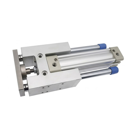
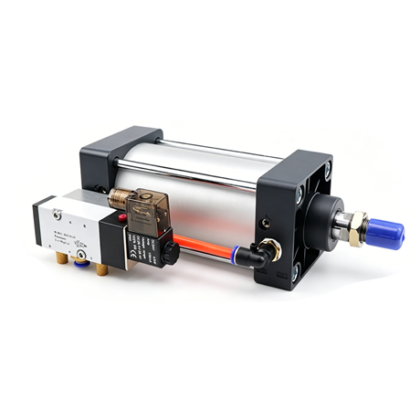
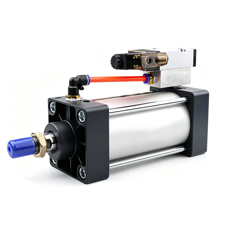
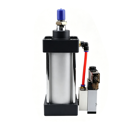
SCF series Pneumatic Cylinder With Solenoid Valve belongs to a derivative series of pneumatic cylinders formed by combining standard SC-series cylinders with solenoid valves.
Technical Parameters
| Pneumatic Cylinder Section | ||||||
| Inner diameter mm (bore diameter) | 32 | 40 | 50 | 63 | 80 | 100 |
| Action Form | Double-acting type | |||||
| Working Medium | Air (filtered through a 40 µm mesh screen) | |||||
| Mounting Configurations | Basic Type FA, FB, CA, CB, LB, TC, TCM1 | |||||
| Operating Pressure Range | 0.15~1.0Mpa(22~145Psi)(1.5~10.0bar) | |||||
| Guaranteed Pressure Resistance | 1.5Mpa(215Psi)(15bar) | |||||
| Operating Temperature | -20°C~70°C | |||||
| Operating Speed Range | 30~800mm/s | |||||
| Travel Range | (0~250 +1.0)(250~1000 +1.5)(1001~1500 +2.0) | |||||
| Buffering Form | Adjustable Cushioning (Air Cushioning) | |||||
| Cushion Stroke (mm) | 21 | 28 | 29 | |||
| Connection Thread Type | بي تي 1/8 | بي تي 1/4 | PT3/8 | بي تي 1/2 | ||
| PU Air Tubing Specifications (Outer Diameter × Inner Diameter) | φ8mmXφ5mm | φ10mmXφ6.5mm | ||||
| Piston Rod Connection Accessories | I: I-Type Joint U: Fish-Eye Joint Y: Y-Type Joint F: Floating Joint | |||||
| Compatible with Magnetic Switches | SC1-U SC1-F CS1-G D-A93 D-M9B D-273 D-M9N DS1-E DMSH CS-9D CS-8G DFSH DFSE | |||||
| Pneumatic Solenoid Valve Section | ||
| الطراز | 4M210-06/4M210-08 | 4M310-08/4M310-10 |
| Working Medium | Air (filtered through a 40 µm mesh screen) | |
| Mode of Action | Internally Piloted | |
| Interface Thread Specifications | Inlet: PT1/4 Outlet: PT1/8 | Inlet: PT3/8 Outlet: PT1/4 |
| Effective Cross-Sectional Area | 4M210-06:14.0mm²(cv=0.78)
4M210-08:16.0mm²(Cv=0.89) |
4M310-08:25.0mm²(cv=1.4)
4M31010:30.0mm²(Cv=1.68) |
| Number of positions | Five-Hole Socket, Two-Gang | |
| Operating Pressure Range | 0.15~0.8Mpa(21~114psi) | |
| Guaranteed Pressure Resistance | 1.2Mpa(175psi) | |
| Operating Temperature | -20°C~70°C | |
| Body Material | Aluminum Alloy | |
| lubricating | Lubricant has been appropriately added internally. | |
| Maximum Operating Frequency | 5 times per second | 4 times per second |
| Solenoid Valve Electrical Parameters | |
| Standard Voltage | AC220V AC110V AC24V DC24V DC12V |
| Operating Voltage Range | AC:±15% DC±:10% |
| power consumption | AC:3.5VA DC:3.0W |
| Protection Level | IP65(DIN40050) |
| Heat Resistance Rating | Grade B |
| Connection Type | DIN Socket-type / Lead-wire type |
| Excitation Time | Less than 0.05 seconds |
Note:
The connection threads are available in PT or G thread types.
If lubricant is applied, operation must not be interrupted; ISO VG32 lubricant (or an equivalent grade) is recommended.
The maximum operating frequency applies under no-load conditions.
Pneumatic Cylinder Stroke
| Inner diameter mm (bore diameter) | Standard Travel Stroke(mm) | shortest Stroke | Maximum Stroke | Permissible Travel | |
| 32 | Standard Model | 50.75.80.100.125.150.160.175.200.250.300.350.400.450.500 | 50 | 1000 | 2000 |
| TC-Type | 100.125.150.160.175.200.250.300.350.400.450.500 | 100 | 1000 | 2000 | |
| 40 50 | Standard Model | 50.75.80.100.125.150.160.175.200.250.300.350.400.450.500.600.700.800.900.1000 | 50 | 1200 | 2000 |
| TC-Type | 100.125.150.160.175.200.250.300.350.400.450.500.600.700.800.900.1000 | 100 | 1200 | 2000 | |
| 63 80 100 | Standard Model | 75.80.100.125.150.160.175.200.250.300.350.400.450.500.600.700.800.900.1000 | 75 | 1500 | 2000 |
| TC-Type | 125.150.160.175.200.250.300.350.400.450.500.600.700.800.900.1000 | 125 | 1500 | 2000 | |
For other special itineraries, please contact our company.
For the output force data of this pneumatic cylinder model, please refer to the output force table for the SC series pneumatic cylinders.
Finished Product Order Code
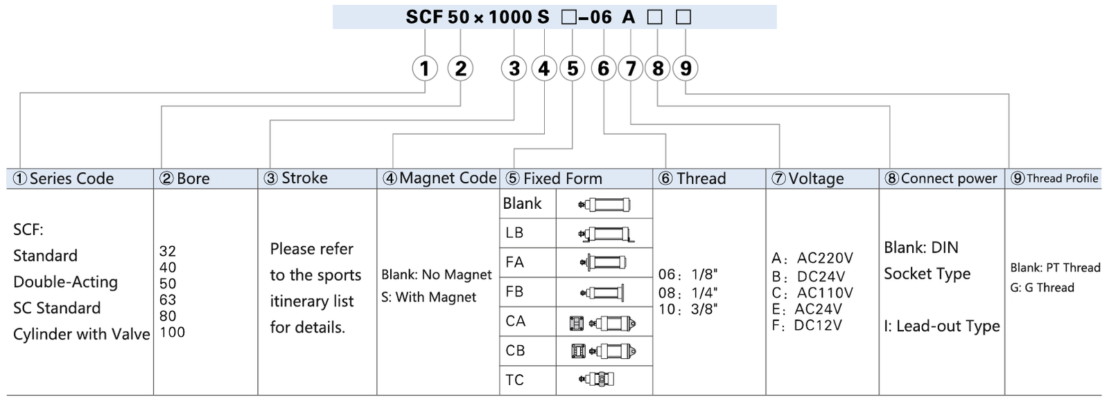
Pneumatic cylinder accessories are compatible with the SAU pneumatic cylinder series.
TC cylinder accessories are designed for use with the TCM1 series.
SCF series Pneumatic Cylinder With Solenoid Valve Main Components
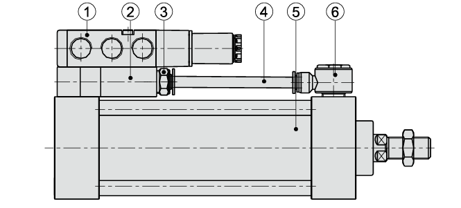
| Serial Number | Product Name | Serial Number | Product Name |
| 1 | 4M Series Pneumatic Solenoid Valves | 4 | Pneumatic Air Hose |
| 2 | Connecting Aluminum Block | 5 | SC Series Standard Cylinders |
| 3 | Straight Pneumatic Fittings (Male) PC | 6 | External Hexagon 90-Degree Elbow Fitting PH |
SCF series Pneumatic Cylinder With Solenoid Valve Dimensional Drawing
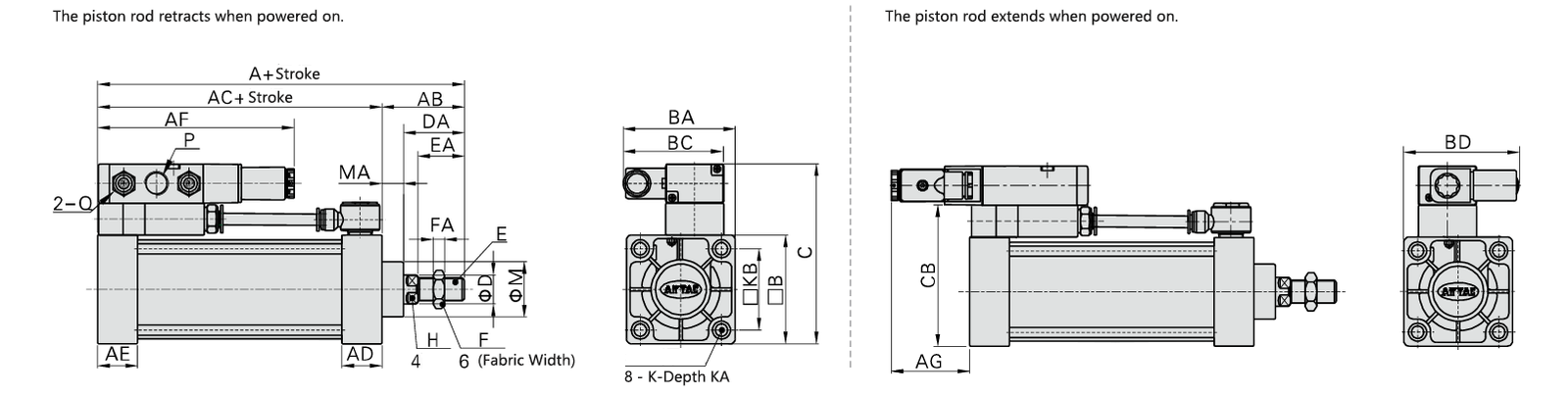
| Bore / Symbol | A | AB | مكيف الهواء | AD | AE | AF | AG | B | BA | BC | BD | C | CB | D | DA | E | EA | F | FA | M | MA |
| 32 | 140 | 47 | 93 | 27.5 | 27.5 | 118 | 53 | 45 | 67 | 67 | 77 | 89 | 67 | 12 | 32 | M10*1.25 | 22 | 17 | 6 | 28 | 15 |
| 40 | 142 | 49 | 93 | 27.5 | 27.5 | 118 | 53 | 50 | 68.5 | 67 | 80.5 | 94 | 72 | 16 | 34 | M12*1.25 | 24 | 17 | 7 | 32 | 15 |
| 50 | 150 | 57 | 93 | 27.5 | 27.5 | 120 | 51 | 62 | 72 | 67 | 89 | 106 | 84 | 20 | 42 | M16*1.5 | 32 | 23 | 8 | 38 | 15 |
| 63 | 153 | 57 | 96 | 27.5 | 27.5 | 135.5 | 54.5 | 75 | 77.5 | 69.5 | 96.5 | 124 | 97 | 20 | 42 | M16*1.5 | 32 | 23 | 8 | 38 | 15 |
| 80 | 182 | 75 | 107 | 33 | 33 | 137 | 53 | 94 | 86.5 | 69.5 | 106.5 | 143 | 116 | 25 | 54 | M20*1.5 | 40 | 26 | 10 | 47 | 21 |
| 100 | 188 | 75 | 113 | 33 | 33 | 135.5 | 54.5 | 112 | 96 | 69.5 | 115 | 161 | 134 | 25 | 54 | M20*1.5 | 40 | 26 | 10 | 47 | 21 |
| Bore / Symbol | Equipped with Solenoid Valve | P | Q | K | KA | KB | H |
| 32 | 4M210-06 | PT18 | بي تي 1/8 | M6*1 | 14.5 | 33 | 10 |
| 4M210-08 | بي تي 1/4 | ||||||
| 40 | 4M210-06 | PT18 | بي تي 1/8 | M6*1 | 14.5 | 37 | 13 |
| 4M210-08 | بي تي 1/4 | ||||||
| 50 | 4M210-06 | PT18 | بي تي 1/8 | M6*1 | 14.5 | 47 | 17 |
| 4M210-08 | بي تي 1/4 | ||||||
| 63 | 4M310-08 | بي تي 1/4 | بي تي 1/4 | M8*1.25 | 14.5 | 56 | 17 |
| 4M310-10 | PT3/8 | ||||||
| 80 | 4M310-08 | بي تي 1/4 | بي تي 1/4 | M10*1.5 | 17 | 70 | 22 |
| 4M310-10 | PT3/8 | ||||||
| 100 | 4M310-08 | بي تي 1/4 | بي تي 1/4 | M10*1.5 | 17 | 84 | 22 |
| 4M310-10 | PT3/8 |
The magnetic and non-magnetic versions share identical dimensions.
SCF series Pneumatic Cylinder With Solenoid Valve Precautions for Use
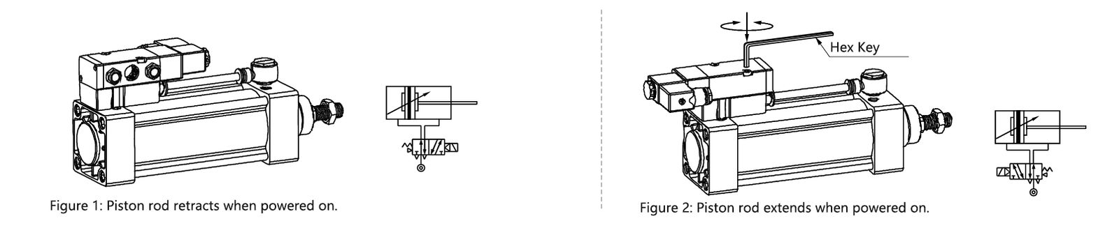
Note: During disassembly and assembly, pay special attention to ensure that the seal between the solenoid valve and the connecting block is in the specified position.
In addition to the information regarding cylinders provided above, the following related details should also be reviewed.
يرجى إرسال
الشركات المصنعة للهواء المضغوط في الصين