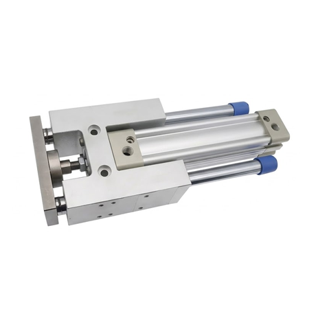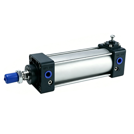
The SCL Series double-acting cylinders with locking mechanisms(SCL Series locking air cylinders) are standard tie-rod type double-acting cylinders.
Equipped with an integrated mechanical locking structure, they enable piston locking at any point along the stroke, thereby preventing cylinder slippage or free-fall in the event of power or air supply failure. These cylinders are characterized by reliable positioning and robust safety protection.
They are ideally suited for automation applications requiring intermediate stopping, load holding, or emergency braking capabilities.
Характеристики
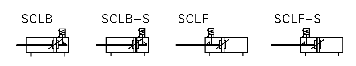
List of Symbols
Technical Specifications
| Bore diameter (mm) | 32 | 40 | 50 | 63 | 80 | 100 |
| Action Form | Standard Double-Acting Type with Lock | |||||
| Working Medium | Clean air (filtered through a screen with a mesh size of 40 µm or larger) | |||||
| Fixed Installation Configuration | FA,FB,CA,B,LB,TC,TCM1 | |||||
| Operating Pressure Range | 0.15~1.0Mpa(22~145Psi)(1.5~10.0bar) | |||||
| Guaranteed Pressure Resistance | 1.5Mpa(215psi)(15bar) | |||||
| Operating Temperature Range | -20°C~70°C | |||||
| Operating Speed Range | 30~800 mm/s | |||||
| Travel Tolerance Range | (0~250 +1.0)(250~1000 +1.5)(1001~1500 +2.0) | |||||
| Buffering Form | Adjustable Cushioning (Air Cushioning) | |||||
| Cushion Stroke: Non-Locking End | 21 | 28 | 29 | |||
| Cushion Stroke: Lock-side | 17 | 18 | 20.5 | 22 | ||
| Connection Thread Diameter | PT1/4 | PT3/8 | PT1/2 | |||
| Piston Rod Connection Accessories | I: I-Type Joint U: Fish-Eye Joint Y: Y-Type Joint F: Floating Joint | |||||
| Compatible with Magnetic Switches | CS1-U,D-A93,D-M9B,DMSG Series,DMSE Series,DMSH Series | |||||
Note: Connecting pipe threads are available in NPT and G thread options.
Standard Travel Range
SCL Series locking air cylinders
| Bore diameter (mm) | Standard Travel Stroke(mm) | Maximum Travel | Permissible Travel |
| 40 | 25.50.75.80.100.125.150.160.175.200.250.300.350.400.450.500.600.700.800 | 1200 | 1800 |
| 50 | 25.50.75.80.100.125.150.160.175.200.250.300.350.400.450.500.600.700.800.900.1000 | 1200 | 1800 |
| 63 | 1500 | 1800 | |
| 80 | 1500 | 1800 | |
| 100 | 1500 | 1800 |
Note:For other special stroke lengths, please contact Wenzhou Maifeng Pneumatic Co., Ltd. (MYFEQD).
The detailed data regarding the theoretical output force of the cylinder is identical to that of the SC Series standard cylinders.
Finished Product Order Code
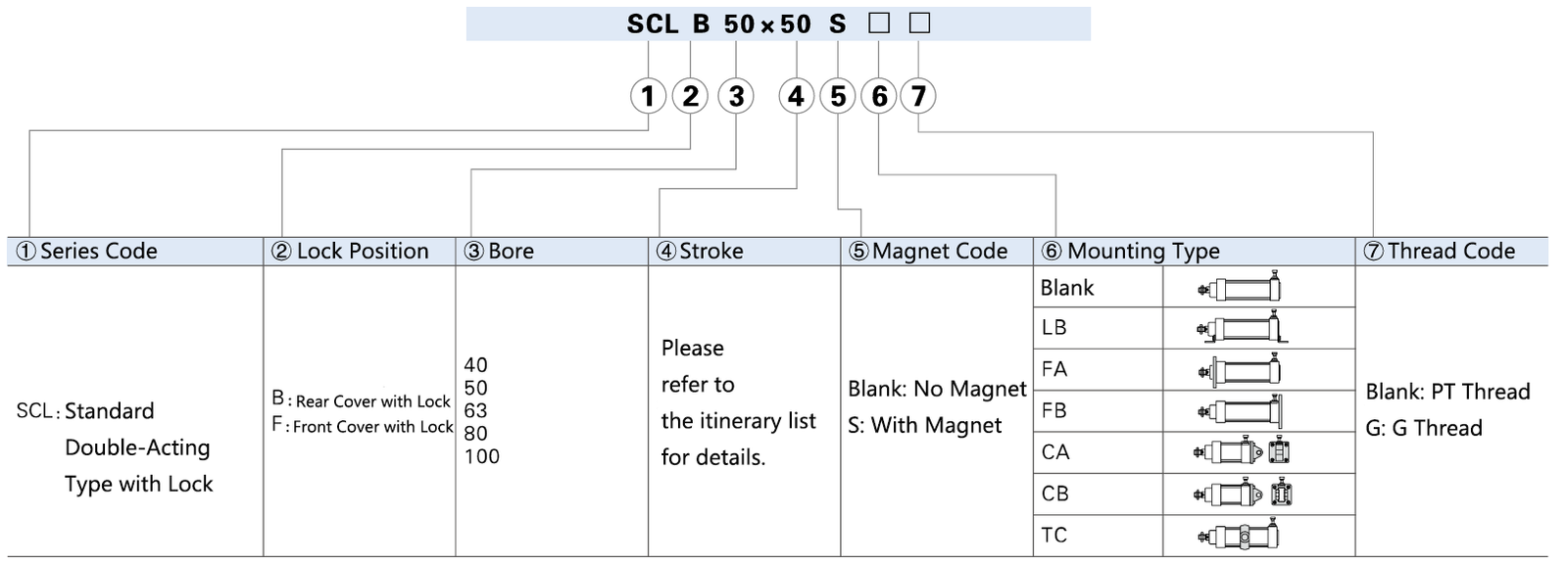
Note: The cylinder mounting accessories are interchangeable with the SAU series, while the TC accessories are designed for use with the TCM1.
Internal Structure and Materials of Main Components
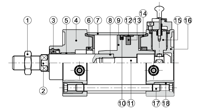
| Item Number | Имя | Material | Item Number | Имя | Material |
| 1 | Nut | Carbon Steel | 10 | Piston O-ring | NBR |
| 2 | Piston Rod | S45 Hard Chrome-Plated Ground Bar | 11 | Plunger | Carbon Steel |
| 3 | Front Cover O-ring | TPU | 12 | Wear Ring | Wear-resistant materials |
| 4 | Front Cover | Aluminum Alloy | 13 | Magnet | Blastic |
| 5 | bushing | Wear-resistant materials | 14 | Buffer Seal | TPU |
| 6 | Buffer O-ring | TPU | 15 | Lock Combination | |
| 7 | Cylinder Block | Aluminum Alloy | 16 | Back Cover | Aluminum Alloy |
| 8 | Piston Rod O-ring | NBR | 17 | Pillar | Carbon Steel |
| 9 | Piston | Aluminum Alloy | 18 | Pillar Nut | Carbon Steel |
SCL Series locking air cylinders Size Information
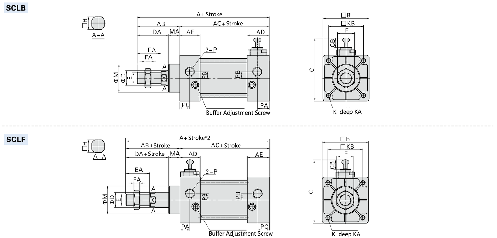
| Bore / Symbol | A | AB | AC | AD | AE | B | C | CB | D | DA | E | EA | F | FA | H | K | KA | KB | M | MA | P | PA | PB | PC |
| 40 | 144.5 | 49 | 95.5 | 30 | 27.5 | 50 | 76.5 | 15 | 16 | 34 | M12*1.25 | 24 | 17 | 7 | 13 | M6*1.0 | 14.5 | 37 | 32 | 15 | PT1/4 | 17.5 | 6 | 15 |
| 50 | 152.5 | 57 | 95.5 | 30 | 27.5 | 62 | 88.5 | 15 | 20 | 42 | M16*1.5 | 32 | 23 | 8 | 17 | M6*1.0 | 14.5 | 47 | 38 | 15 | PT1/4 | 17.5 | 8.5 | 17 |
| 63 | 157 | 57 | 100 | 31.5 | 27.5 | 75 | 100.5 | 14 | 20 | 42 | M16*1.5 | 32 | 23 | 8 | 17 | M8*1.25 | 14.5 | 56 | 38 | 15 | PT3/8 | 18 | 9.5 | 15 |
| 80 | 188 | 75 | 113 | 39 | 33 | 94 | 122.5 | 15 | 25 | 54 | M20*1.5 | 40 | 26 | 10 | 22 | M10*1.5 | 17 | 70 | 47 | 21 | PT3/8 | 25.5 | 10 | 19.5 |
| 100 | 194 | 75 | 119 | 39 | 33 | 112 | 140.5 | 15 | 25 | 54 | M20*1.5 | 40 | 26 | 10 | 22 | M10*1.5 | 17 | 84 | 47 | 21 | PT1/2 | 22.5 | 7 | 16.5 |
The dimensions are identical for both the magnetic and non-magnetic versions.
Usage and Maintenance
1. In the Locked State: If pressure is applied to Port A while neither of the side ports is pressurized, there is a significant risk—such as the locking mechanism failing to disengage or suddenly releasing—that could result in the piston rod being violently ejected.
When disengaging the locking mechanism, it is imperative to apply pressure to Port B and to ensure that the mechanism is released while under a no-load condition.
2. If a quick exhaust valve is used to accelerate the retraction speed, the cylinder body may sometimes begin to move before the locking pin disengages, thereby preventing proper unlocking.
Therefore, please do not use quick exhaust valves with locking cylinders.
3. Please do not use this product in combination with 3-way solenoid valves (particularly the center-closed metal-seal type).
If pressure remains trapped within the air port of the unit equipped with a locking mechanism, the locking function will not engage.
Furthermore, even if the unit does lock, air leaking from the solenoid valve will continue to enter the cylinder, causing the lock to disengage after a period of time.
4. If the locking mechanism is subjected to back pressure during operation, it may occasionally disengage.
Therefore, please use a standalone or integrated solenoid valve featuring individual exhaust ports.
5. In the case of a cylinder equipped with adjustable cushioning, if the cushion needle valve of the locking mechanism is overtightened, the piston may sometimes bind at the end of its stroke, potentially leading to damage to the locking mechanism.
Therefore, the needle valve should be adjusted to ensure that the piston does not bind.
6. Upon completing manual operation of the locking mechanism, be sure to return the manual device to its original position.
Furthermore, please refrain from performing manual operations at any time other than during adjustment, as doing so poses a safety risk.
7. When adjusting the cylinder mounting machine, please release the lock. Performing installation or similar operations while the unit is in the locked state will result in damage to the locking mechanism.
8. Under no circumstances should you use more than two pneumatic cylinders with locks to simultaneously drive a single workpiece; doing so may occasionally result in one of the cylinders failing to unlock.
9. Please use the speed control valve in the exhaust throttling mode; in the intake throttling mode, it may sometimes be impossible to release the lock.
10. When operating the unit with the locking mechanism, please ensure that the cylinder is utilized to the full extent of its stroke. If the cylinder piston does not reach the end of its stroke, the locking mechanism may fail to engage or disengage.
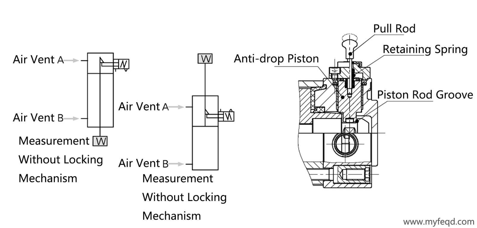
11. Manual Method for Releasing the Non-Locking Mechanism:
Thread the pull rod into the anti-drop piston, then apply a force of at least 20 N to pull the bolt outward; once the anti-drop piston shifts, the lock is released.
(This applies when the unit is mounted horizontally under no-load conditions, or when the air port on the opposite side is pressurized.) Alternatively—or upon releasing the pull rod—the anti-drop piston returns to its original position driven by the action of the stopper spring, engages with the groove in the piston rod, and the piston enters the locked state.
In addition to the information regarding cylinders provided above, the following related details should also be reviewed.